Header Graphic
Apps for iPad

FAA Glossaries

Touring Machine Company

Aviation Weather Services – Observed Text Products

June 22nd, 2008

Aviation Routine Weather Report (METAR)

Aviation Routine Weather Report (METAR) is the primary observation code used in the U. S. to satisfy World Meteorological Organization (WMO) and International Civil Aviation Organization (ICAO) requirements for reporting surface meteorological data. A METAR report includes the airport identifier, time of observation, wind, visibility, runway visual range, present weather phenomena, sky conditions, temperature, dew point, and altimeter setting.

Selected Special Weather Report (SPECI)

A Selected Special Weather Report (SPECI) is an unscheduled report taken when any of the criteria given in Table 3-1 are observed during the interim period between the hourly reports. SPECI contains all data elements found in a METAR plus additional plain language information which elaborates on data in the body of the report. All SPECIs are made as soon as possible after the relevant criteria are observed. Whenever SPECI criteria are met at the time of the routine METAR, a METAR is issued.

Pilot Weather Reports (PIREP)

No report is timelier than the one made from the flight deck of aircraft in flight. In fact, aircraft in flight are the only means of observing actual icing and turbulence conditions. … Pilots should report any observation, good or bad, to assist other pilots with flight planning and preparation. If conditions were forecasted to occur but not encountered, a pilot should also report this inaccuracy.

Knowledge Tests often have questions on reporting the degree of turbulence. The levels are described in this chart.

PIREP Turbulence


Radar

Radar images are graphical displays of precipitation and non-precipitation targets detected by weather radar. WSR-88D Doppler radar displays these targets on a variety of products which can be found on the internet on the National Weather Service (NWS) Doppler Radar Images web site.

The colors on radar images represent different echo reflectivities (intensities) measured in dBZ
(decibels of Z). The dBZ values increase based on the strength of the return signal from targets
in the atmosphere. Each reflectivity image includes a color scale that represents a correlation
between reflectivity value and color on the radar image.

Base Reflectivity

Base Reflectivity is a display of both the location and intensity of reflectivity data. Base Reflectivity images encompass several different elevation angles (tilts) of the antenna. The Base Reflectivity image currently available on the ADDS website begins at the lowest tilt angle (0.5°), more specifically 0.5° above the horizon.

The Base Reflectivity product can be used to determine the location of precipitation and non- precipitation echoes, the intensity of liquid precipitation, and the general movement of precipitation when animating the image.

Composite Reflectivity

Composite reflectivity is the maximum echo intensity (reflectivity) detected within a column of the atmosphere above a location. The radar scans through all of the elevation slices to determine the highest dBZ value in the vertical column then displays that value on the product. When compared with Base Reflectivity, the Composite Reflectivity can reveal important storm structure features and intensity trends of storms….The primary use of the Composite Reflectivity product, which offers the highest reflectivity value in a vertical column, is to determine the vertical structure of the precipitation.


Satellite

Satellite is perhaps the single most important source of weather data world wide, particularly over data sparse regions such as countries without organized weather data collection and the oceans.
GOES satellite imagery can be found on the NWS Aviation Digital Data Service (ADDS) website.

Imagery Types

Three types of satellite imagery are commonly used: Visible, infrared (IR), and water vapor. Visible imagery is available only during daylight hours. IR and water vapor imagery are available day or night.

Visible Imagery

Visible imagery displays reflected sunlight from the Earth’s surface, clouds, and particulate matter in the atmosphere. These images are simply black and white pictures of the Earth from space. During daylight hours, visible imagery is the most widely used image type.

Infrared (IR) Imagery

Infrared (IR) images display temperatures of the Earth’s surface, clouds, and particulate matter. Generally speaking, the warmer an object, the more infrared energy it emits. The satellite sensor measures this energy and calibrates it to temperature using a very simple physical relationship.

Clouds that are very high in the atmosphere are generally quite cold (perhaps -50°C) whereas clouds very near the earth’s surface are generally quite warm (perhaps +5°C). Likewise, land may be even warmer than the lower clouds (perhaps +20°C). Those colder clouds emit much less infrared energy than the warmer clouds and the land emits more than those warm clouds.

The data measured by satellite is calibrated and colorized according to the temperature. If the temperature of the atmosphere decreases with height (which is typical), cloud-top temperature can be used to roughly determine which clouds are high-level and which are low-level.

When clouds are present, the temperature displayed on the infrared images is that of the tops of clouds. When clouds are not present, the temperature is that of the ground or the ocean.

Water Vapor Imagery

The water vapor imagery (Figure 4-25 and Figure 4-26) displays the quantity of water vapor generally located in the middle and upper troposphere within the layer between 700 millibars (FL100) to 200 millibars (FL390). The actual numbers displayed on the water vapor images correspond to temperature in degrees Celsius. No direct relationship exists between these values and the temperatures of clouds, unlike IR imagery. Water Vapor imagery does not really “see” clouds but “sees” high-level water vapor instead. The most useful information to be gained from the water vapor images is the locations and movements of weather systems, jet streams, and thunderstorms.

In general, regions displayed in shades of red are VERY dry in the upper atmosphere and MAY correlate to crisp blue skies from a ground perspective. On the contrary, regions displayed in shades of blue or green are indicative of lots of high-level moisture and may also indicate cloudiness. This cloudiness could simply be high-level cirrus types or thunderstorms.


GRAPHICAL OBSERVATIONS AND DERIVED PRODUCTS

Surface Analysis Charts

Surface Analysis charts are analyzed charts of surface weather observations. The chart depicts the distribution of several items including sea level pressure, the positions of highs, lows, ridges, and troughs, the location and character of fronts, and the various boundaries such as drylines, outflow boundaries, sea-breeze fronts, and convergence lines. Other symbols are often added depending upon the intended use of the chart. Pressure is referred to in mean sea level (MSL) on the surface analysis chart while all other elements are presented as they occur at the surface point of observation. A chart in this general form is commonly referred to as the weather map… [They] are issued eight times daily.

[These symbols are good to know. ]
Surface Analysis Symbols

The approximate amount of sky cover can be determined by the circle at the center of the station plot. The amount the circle is filled reflects the amount of sky covered by clouds.

Surface Analysis Wind Depiction

The analysis shows positions and types of fronts by the symbols in Figure 5-2. The symbols on
the front indicate the type of front and point in the direction toward which the front is moving.
Two short lines across a front indicate a change in front type. [Note that that visibility is not reported if it is unlimited and ceilings are only given if they exist.]

Surface Analysis Sample

Analyses

Isobars, pressure systems, and fronts are the most common analyses depicted on the surface analysis charts. An isobar is a line of equal or constant pressure commonly used to analyze pressure patterns. [Note: These items are not observations but estimates of weather based on the observations at the reporting stations.]


Constant Pressure Charts

Constant pressure charts are maps of selected conditions along specified constant pressure surfaces (pressure altitudes) and depict observed weather. Constant pressure charts help to determine the three-dimensional aspect of depicted pressure systems. Each chart provides a plan-projection view at a specified pressure altitude.

Height

Heights are analyzed with contours. Contours are lines of constant height in MSL and are used to map height variations of constant pressure surfaces. They identify and characterize pressure systems on constant pressure charts.
Wind speeds are directly proportional to contour gradients. Faster wind speeds are associated with strong contour gradients and slower wind speeds are associated with weak contour gradients. In mountainous areas, winds are often variable on constant pressure charts with altitudes near terrain elevation due to friction.

Temperature

Temperature is analyzed with isotherms which are lines of constant temperature. Temperature gradient is the amount of temperature change over a specified distance. Isotherm gradients identify the magnitude of temperature variations. Strong gradients are denoted by closely spaced isotherms and identify large temperature variations. Weak gradients are denoted by loosely spaced isotherms and identify small temperature variations.

Wind Speed

Wind speed is analyzed with isotachs which are lines of constant wind speed. They are drawn on the 300-mb and 200-mb charts with short-dashed lines at 20-knot intervals beginning with10 knots. They are labeled with a two- or three-digit number followed by a K for knots. Regions of high wind speeds are highlighted by alternate bands of shading and no-shading at 40-knot intervals beginning at 70 knots. A jet stream axis is the axis of maximum wind speed in a jet stream. Jet axes are not explicitly indicated, but their positions can be inferred from the isotach pattern and plotted winds.

Use

Constant pressure charts are used to provide an overview of selected observed weather conditions at specified pressure altitudes.Pressure patterns cause and characterize much of the weather. Typically, lows and troughs are associated with bad weather, clouds and precipitation, while highs and ridges are associated with good weather.


Freezing-level Graphic

The freezing level is the lowest altitude in the atmosphere over a given location at which the air temperature reaches 0ºC. This altitude is also known as the height of the 0ºC constant- temperature surface. A freezing level chart shows the height of the 0ºC constant-temperature surface.

The initial analysis and 3-hour forecast graphics are updated hourly. The 6-, 9-, and 12-hour forecast graphics are updated every three hours.

Freezing level graphics are used to assess the lowest freezing level heights and their values relative to flight paths. Clear, rime and mixed icing are found in layers with below-freezing (negative) temperatures and super-cooled water droplets. Users should be aware that official forecast freezing level information is specified within the AIRMET Zulu Bulletins .

Freezing Level


Lifted Index (LI)

The Lifted Index is a common measure of atmospheric stability. The Lifted Index Analysis Chart depicts a number associated with the stability of a surface parcel of air lifted to 500 mb.


Weather Depiction Chart

The Weather Depiction Chart (Figure 5-39) contains a plot of weather conditions at selected METAR stations and an analysis of weather flying category. It is designed primarily as a briefing tool to alert aviation interests to the location of critical or near-critical operational minimums at terminals in the conterminous US and surrounding land areas. The Weather Depiction chart is issued eight times daily.

Weather Depiction Chart-Sample

METAR elements associated with weather flying category (visibility, present weather, sky cover, and ceiling) are plotted for each station on the chart.

Weather Depiction Chart

Weather Flying Category Analysis

Instrument Flight Rules (IFR) indicated on the Weather Depiction Chart represents ceilings less than 1,000 feet and/or visibility less than 3 statute miles and IFR operations must be in place. IFR areas are outlined on the chart with a solid line and are shaded. IFR areas are typically shaded red in colorized versions of the chart.

Marginal Visual Flight Rules (MVFR) indicated on the Weather Depiction Chart represents ceiling 1,000 to 3,000 feet and/or visibility 3 to 5 statute miles and VFR operations can take place. MVFR areas are outlined with a solid line, but the area is not shaded. MVFR areas are typically shaded blue in colorized versions of the chart.

Visual Flight Rules (VFR) indicated on the Weather Depiction Chart represents a ceiling greater than 3,000 feet or clear skies and visibility greater than 5 statute miles and VFR operations can take place. VFR conditions are not analyzed. This does not necessarily imply that the sky is clear.

Use

The Weather Depiction Chart is an ideal place to begin flight planning or to prepare for a weather briefing. This chart provides an overview of weather flying categories and other adverse weather conditions for the chart valid time. The chart, though, may not completely represent the en route conditions because of terrain variations and the possibility of weather occurring between reporting stations. This chart should be used in addition to the current METAR reports, pilot weather reports, and radar and satellite imagery for a complete look at the latest flying conditions.


Radar Summary Chart

The Radar Summary Chart (Figure 5-49) is a computer-generated mosaic of radar echo intensity contours based on Radar Weather Reports (Section 2.3) over the contiguous U.S. Possible precipitation types, cell movements, maximum tops, locations of line echoes, and remarks are plotted on this chart. Much of this information is often truncated due to space limitations. Severe thunderstorm and tornado watches are plotted if they are in effect when the chart is valid. … The chart is issued hourly. … The Radar Summary Chart depicts precipitation type, intensity, coverage, movement, echoes, and maximum tops.

Radar Summary Sample

Precipitation Type

The precipitation type, determined by a computer model, is indicated on the chart by symbols located adjacent to the precipitation areas. These symbols (Table 5-20) are not in METAR format. Freezing precipitation is not reported in Radar Weather Reports and, thus, not plotted on the Radar Summary Chart.

Radar Summary Precipitation

Radar Summary Intensity

Cell Movement

Cell movement is the average motion of all cells within a configuration. An arrow indicates direction of cell movement. Speed in knots is entered near the arrowhead. LM identifies little movement. Movement of areas and lines can be significantly different from the motion of the individual cells that comprise these configurations.

MaximumTop

Tops are plotted in 3-digit groups representing height in hundreds of feet MSL and are underlined. Where it is necessary to offset a top for reasons of insufficient space, a line is drawn from one end of the underline to a small black square which represents the location of the top. Maximum echo top does not equal maximum cloud top. The maximum echo top is the altitude of the highest light precipitation echo, not highest cloud top.

Weather Watch Areas

Heavy dashed lines outline Tornado (WT)and Severe Thunderstorm (WS) Watch areas. The type of watch and the watch number are enclosed in a rectangle and positioned as closely as possible to the northeast corner of the watch. If there is no room at the northeast corner of the watch, the watch information is offset and connected to the watch by a thin line.

Use

The Radar Summary Chart aids in preflight planning by identifying areas of precipitation and highlighting its characteristics. This chart displays precipitation only; it does not display clouds, fog, fronts, or other boundaries. Therefore, the absence of echoes does not equal clear weather. Cloud tops will be somewhat higher than precipitation tops detected by radar. The chart must be used in conjunction with other charts, reports, and forecasts.

The radar summary chart is for preflight planning only and should always be cross-checked and updated by current WSR-88D images. Once airborne, the pilot must evade individual storms by in-flight observations. This can be done by using visual sighting or airborne radar as well as by requesting weather radar information from En route Flight Advisory Service “Flight Watch” briefers at Automated Flight Service Station (AFSS). AFSS Flight Watch briefers have access to current weather radar imagery.

Aviation Weather Services – Overview

June 22nd, 2008

There are lots of sources for aviation weather and I cover them in some detail in this post. The National Weather Service publishes weather observations for aviators and publishes most of them at the Standard Briefing page. Most of them are covered in the FAA publication Aviation Weather Services AC 00-45F. The 2007 version of this document can be found here. Some of the observations and forecasts are easy to understand and some take a bit of work to decipher. The Aviation Weather Services booklet does a good job of explaining how to interpret the weather products and I’d recommend that you read it if the legends on the web site aren’t clear.

The FAA Knowledge Tests on the other hand, are often less than straightforward. For example, one question on the private pilot exam is:

From which primary source should information be obtained regarding expected
weather at the estimated time of arrival if your destination has no Terminal Forecast?
      A. Low-Level Prognostic Chart.
      B. Weather Depiction Chart.
      C. Area Forecast.

All of these products will give you some information on the weather at your destination when you arrive. However, only a careful reading of the question and knowledge of the exact wording of what is contained in the weather product will give you the correct answer.

As described in the AWS document, the Weather Depiction Chart is based on METARs and gives weather at the time the chart was made. It is updated eight times a day, so reviewing it several times before a flight will give a good indication of what is happening at your destination. This is probably not the right answer since the question is probably looking for a forecast product.

Short-Range Surface Prognostic (Prog) Charts provide a forecast of surface pressure systems, fronts and precipitation for a 2-day period. The forecast area covers the 48- contiguous states, the coastal waters and portions of adjacent countries. The forecasted conditions are divided into four forecast periods, 12-, 24-, 36-, and 48-hours. Each chart depicts a “snapshot” of weather elements expected at the specified valid time. Reviewing these forecasts would give an excellent overview of what to expect at your destination. It is missing temperatures and wind. which would be available on a TAF.

The FA [Area Forecast] contains forecast information for VFR/MVFR clouds and weather for a 12-hour period with a 12- to 18-hour categorical outlook forecast for IFR, MVFR, and/or VFR. The following weather elements are included in the 12-hour forecast:

  • Thunderstorms and precipitation;
  • Sky condition (cloud height, amount, and tops) if bases are at or below (AOB) FL180 MSL. (Tops will only be forecast for broken (BKN) or overcast (OVC) clouds);
  • Obstructions to visibility (fog, mist, haze, blowing dust, etc.) if surface visibilities are three (3) to six (6) miles; and
  • Sustained surface wind speed of 20 knots or greater.

This product contains the detailed information for 12 hours and more general information (VFR/IFR) for the next six hours. It contains precipitation, sky cover, and significant wind so it covers most of the information for a TAF.

The best answer, in my opinion, would be to check the TAFs at nearby airports, especially ones that share weather patterns. That isn’t an option, so I’d go with the Area Forecast since it has the most information contained in a TAF.

However, page 7-1 of the Aviation Weather Services book says:

To understand the complete weather picture, the FA must be used in conjunction with the AIRMETs and SIGMETs. Together, they are used to determine forecast en route weather and to interpolate conditions at airports for which no Terminal Aerodrome Forecasts (TAFs) are issued.

The point here is that the questions on the test don’t necessarily reflect how the products will be used, but often hinge on obscure differences between the weather products and a single phrase in the book. This the first of a series of posts that summarize the information in the Aviation Weather Services booklet. I hope it will make it easier to answer the test questions. It might even help you make sense of the different products that are available.


Aviation Weather Center
CLASSIFICATION OF AVIATION WEATHER PRODUCTS.
A. The development of new aviation weather products is an evolutionary process with distinct stages of product maturity. The growing demand for new weather products and the corresponding increase in research and development to meet that demand, along with relatively unfettered access to weather information via the public Internet, created confusion within the aviation community regarding the relationship between regulatory requirements and new weather products. Consequently, the FAA finds it necessary to differentiate between those weather products that may be used to comply with regulatory requirements and those that may only be used to improve situational awareness. To clarify the proper use of aviation weather products to meet the requirements of the regulations, the FAA developed the following definitions:

Primary Weather Product. An aviation weather product that meets all the regulatory requirements and safety needs, for use in making flight-related aviation weather decisions.

Supplementary Weather Product. A aviation weather product that may be used for enhanced situational awareness. If used, a supplementary weather product must only be used in conjunction with one or more primary weather products. In addition, the FAA may further restrict the use of supplementary weather products through limitations described in the product label.

NOTE: An aviation weather product produced by the Federal Government is a primary product unless designated as a supplementary product by the FAA.

B. In developing the definitions of primary and supplementary weather products, it is not the intent of the FAA to change or increase the regulatory burden upon certificate holders. Rather, the definitions are meant to eliminate confusion by differentiating between products that may be used to meet regulatory requirements and other products that may only be used to improve situational awareness.

C. All flight-related, aviation weather decisions must be based on primary weather products. Supplementary weather products augment the primary products by providing additional weather information, but may not be used as stand-alone products to meet aviation weather regulatory requirements or without the relevant primary products. When discrepancies exist between primary and supplementary products pertaining to the same weather phenomena, users must base flight-related decisions on the primary weather product. Furthermore, multiple primary products may be necessary to meet all aviation weather regulatory requirements.

D. As previously noted, the FAA may choose to restrict certain weather products to specific types of usage or classes of user. Any limitations imposed by the FAA on the use of a product will appear in the product label.

Types of Aviation Weather Information

The FAA has identified the following three distinct types of weather information that may be needed to conduct aircraft operations: observations, analyses, and forecasts.

Observations

Observations are raw weather data collected by some type of sensor(s). The observations can either be in situ (e.g. surface or airborne) or remote (e.g. weather radar, satellite, profiler, and lightning).

Analysis

Analyses of weather information are an enhanced depiction and/or interpretation of observed weather data.

Forecasts

Forecasts are the predictions of the development and/or movement of weather phenomena based on meteorological observations and various mathematical models.

In-flight weather advisories, including Significant Meteorological Information (SIGMET), Convective SIGMETs, Airman’s Meteorological Information (AIRMET), Center Weather Advisories (CWA), and Meteorological Impact Statements (MIS), are considered forecast weather information products.

VOR’s, GPS, and Magnetic Variation

June 19th, 2008

Why is there a difference between the magnetic variation for the airport and the VOR located at the same airport?

When a navaid is first constructed, the antenna is physically oriented to True North. Then a potentiometer adjustment is made to slave the navaid with Magnetic North. This action matches the isogonic line making it agree with a magnetic compass. Initially these two values are the same, but the magnetic variation of the earth changes at differing rates depending upon location and time. Navaids are commissioned and remain online 24 hours per day 365 days per year. Although periodic maintenance is performed as needed, a re-slaving to match the isogonic value requires a total navaid shut down, re-alignment and a re-certification flight check. Only when the navaid is out of tolerance by at least +/-6 degrees will a re-slaving procedure be initiated allowing the navaid and airport magnetic variation to match again.

Note: GPS databases use a MAGVAR model to calculate the most up-to-date magnetic variation.

FAA Aviation System Standards Link

AIM 1-1-19. Global Positioning System (GPS)

l. Conventional Versus GPS Navigation Data

There may be slight differences between the course information portrayed on navigational charts and a GPS navigation display when flying authorized GPS instrument procedures or along an airway. All magnetic tracks defined by any conventional navigation aids are determined by the application of the station magnetic variation. In contrast, GPS RNAV systems may use an algorithm, which applies the local magnetic variation and may produce small differences in the displayed course. However, both methods of navigation should produce the same desired ground track when using approved, IFR navigation system. Should significant differences between the approach chart and the GPS avionics’ application of the navigation database arise, the published approach chart, supplemented by NOTAMs, holds precedence.

Due to the GPS avionics’ computation of great circle courses, and the variations in magnetic variation, the bearing to the next waypoint and the course from the last waypoint (if available) may not be exactly 180° apart when long distances are involved. Variations in distances will occur since GPS distance-to-waypoint values are along-track distances (ATD) computed to the next waypoint and the DME values published on underlying procedures are slant-range distances measured to the station. This difference increases with aircraft altitude and proximity to the NAVAID.

Altimeter Reading at Non-standard Temp and Pressure

May 29th, 2008

There are lots of questions on the FAA Knowledge Tests about altimeter readings at non-standard temperature and pressure settings. The non-standard pressure questions are fairly intuitive. We all know that pressure decreases as altitude increases. Therefore, if the pressure is lower than what the altimeter expects, the altimeter is fooled into thinking it is higher than it actually is. Likewise, if the pressure is higher than standard, the altimeter reads lower than it should.

Dramatic and dangerous effects most commonly occur when crossing a frontal boundary from an area of high pressure to an area of low pressure. If the altimeter is set to the local altimeter setting in the area of high pressure and the aircraft flies to an area of low pressure, without changing the altimeter setting, the altimeter reading will be too high, possibly by hundreds of feet. Less dramatic changes happen all the time when you fly. As an example, right now the altimeter setting at KSBP is 30.08. The setting at KSBA (62 nm away) is 30.01. If you fly to KSBA you would notice a change in altitude of -70 feet when you get the new altimeter setting from approach control. The aircraft is 70 feet lower than you thought. That is the origin of the memory aid, “HIGH TO LOW LOOK OUT BELOW”.

AIM 7−2−3. Altimeter Errors
b. Once in flight, it is very important to obtain frequently current altimeter settings en route. If you do not reset your altimeter when flying from an area of high pressure into an area of low pressure, your aircraft will be closer to the surface than your altimeter indicates. An inch error in the altimeter setting equals 1,000 feet of altitude. To quote an old saying: “GOING FROM A HIGH TO A LOW, LOOK OUT BELOW.”

Instrument Procedures Handbook
When cruising below 18,000 feet MSL, the altimeter must be adjusted to the current setting, as reported by a station within 100 NM of your position. In areas where weather-reporting stations are more than 100 NM from the route, the altimeter setting of a station that is closest may be used.

You will notice that, when using flight following or flying IFR, after checking in with a new controller, the controller will usually respond to your check-in with the altimeter setting he is using for flights in your area.

Non-standard Temperature
The same thing happens with temperature changes but it is less intuitive because we don’t have day-to-day experience with changing the altimeter with variations in temperature. We also learned about combustion in the engine and associate high temperatures with high pressures and that can lead to us getting tangled up in our thought process. Lets start from scratch and build a mental model of how the altimeter works.

Think of the aircraft as siting in a column of air. The altimeter measures the weight of the air above the aircraft. It doesn’t really know how much air is below it or how high it is above the ground. It just knows that at a certain pressure from the air above it makes it read a specified height. It has been calibrated for standard temperature and pressure lapse rates. If the temperature or pressure don’t change as expected, the weight of the air above it will not be the same as it is calibrated for, and it will give erroneous readings.

Let’s start our thought experiment with temperature and pressure at standard (29.92″ and 15°C) and the aircraft at 5,000′ MSL and AGL. Now imagine that the entire air mass being heated to be warmer than standard temperature. We know from high school physics that air expands as the temperature goes up. The entire column of air now expands and as the column of air expands, the aircraft moves higher in the column. Note that the weight of the air above the aircraft hasn’t changed, it just takes up more room. Since the weight of the air hasn’t changed, the altimeter reading hasn’t changed. The aircraft is now at a higher AGL than it was before but the altimeter still says 5,000′ MSL.

Non-standard Temperature

The reverse occurs when air temperature is lower than standard. As shown on the graphic above, the altimeter will read lower than it should if the air temperature is colder than standard. The same memory aid we used with pressure applies, “HIGH TO LOW LOOK OUT BELOW”.

People often get the impact backwards when they try to relate it to knowledge of engine combustion. In an engine, higher temperatures indicate higher pressures. So they think that if the temperature is higher, then pressure is higher. Normally higher pressure means altimeter reading is lower. The reason higher temperatures equate to higher pressures in an engine cylinder is because of the ideal gas law PV= nRT. For a fixed volume, higher temperature means higher pressure. But the volume is not fixed in the atmosphere, so the reasoning doesn’t translate directly to this problem.

For those who care, the standard corrections for temperature are: For each 10° C the OAT is warmer than ISA increase the indicated altitude by 4% to give true altitude. For each 10° C the OAT is cooler than ISA decrease the indicated altitude by 4%.

Turbocharging/Turbonormalizing

May 29th, 2008

Turbocharging and turbonormalizing allow an airplane to maintain sea-level power at higher altitudes. Both work on the same principle, exhaust gases turn a turbine that compresses the air that is fed into the engine. The compressed air contains more oxygen so more fuel can be burned resulting in more power. Turbonormalizing increases the air pressure to sea-level pressure. Turbocharging (also called turbosupercharging) can increase the air pressure to 6-10 inches above sea-level pressure. Otherwise they are the same. Turbocharging is especially useful when taking off at high density altitude and when climbing above mountains or weather.

This article—AOPA: Turbonormalizing improves an airplane’s utility—at AOPA is a good overview of turbonormalizing as done by Tornado Alley Turbo.

This article—AOPA Online: Turbonormalizing—goes into the benefits of tubonormalizing.

Tornado Alley Turbo explain in detail how to operate their turbonormalized conversion in this article—Operation of the Turbonormalized (TN) IO-520/550 . They recommend lean of peak operation at full throttle using the mixture to control Turbine Inlet Temperature (TIT) and Cylinder Head Temperature (CHT).

This article in Plane and Pilot gives some examples of when a turbo can come in handy—Compress Your Power. This one by Mike Busch—Turbocharging and Pressurization: An Analysis of the Benefits, Costs, and Disadvantages—discusses the advantages and costs concludes that there is a tremendous benefit for serious travelers.

For those of you who like details, this article—Troubleshooting the Turbo-System by Mike Busch explains how the turbo system works and describes the operation of the system in different phases of flight.

Kelly Aerospace has some PDFs on turbo maintenance and troubleshooting—Tech Info


Turbo This is an image of a turbo on a TSIO-360. The housing contains the blades. The orange hose is for oil.


Overboost Control Valve Overboost Control Valve Overboost Control ValveThese are examples of the overboost control valve. It is located on the intake after the compressor outlet and before the carburetor or fuel injector. It prevents surges in pressure from reaching the engine. Overboost can be minimized by making sure the oil has reached operating temperature before takeoff. It can occur when the throttle is advanced quickly for a go-around and the prop governor lags or the wastegate sticks.


Turbo Cover This is an image of a turbo on a TSIO-360. The housing is being removed showing the turbine blades. The orange/red parts on the end of the hoses are check valves for oil. Check valves are often installed into supply and drain lines of turbocharger oil systems to prevent oil from seeping by gravity (after shutdown) into the bearing housing to a level above the seals, causing oil to leak into exhaust and induction systems. Inlet check valves are, usually, the spring loaded ball-and-socket type. Pressures vary; refer to operator’s manual for proper procedure. Outlet check valves will, usually, have spring tensioned valves which will close in the abscence of flowing oil. Check outlet valve for spring tension. Replace if faulty.


Turbo These blades turn at 50,000-100,000 rpm and are driven by the exhaust gas. At all inspections the blades must be checked for for potential foreign object damage (FOD). The outer tips and adjacent housing surfaces must be checked for any evidence of drag or rubbing. The blades on the turbine get very hot and are spinning very fast so there is a tendency for the blades to stretch over time.


Turbo Another image of the turbo and associated hardware for attaching the housing.


Turbo BladesThe impeller blades compress the intake air before it is sent to the engine. One of the checks that you perform at an annual or 100-hours inspection is to make sure they turn freely. In this case they did not, so the turbo was removed and inspected. It would not turn freely and was sent out for refurbishment.


Waste Gate This is a wastegate. Exhaust gases bypass the turbine and go directly out the exhaust. The configuration is different for different aircraft and engines.


Required Documents—In the Aircraft

May 29th, 2008

Students are taught the mnemonic ARROW—Airworthiness Certificate, Registration, Radio License, Operating Limitations, Weight and Balance for remembering the required documents. This article discusses the regulations behind the mnemonic and expands a bit on what is meant.

Airworthiness Certificate and Registration

These are fairly straightforward. Every aircraft has an airworthiness certificate issued by the manufacturer and must have a current FAA registration. Information on registrations can be found at this FAA web site.

14 CFR § 91.203 Civil aircraft: Certifications required.

(a) Except as provided in §91.715, no person may operate a civil aircraft unless it has within it the following:

(1) An appropriate and current airworthiness certificate. Each U.S. airworthiness certificate used to comply with this subparagraph (except a special flight permit, a copy of the applicable operations specifications issued under §21.197(c) of this chapter, appropriate sections of the air carrier manual required by parts 121 and 135 of this chapter containing that portion of the operations specifications issued under §21.197(c), or an authorization under §91.611) must have on it the registration number assigned to the aircraft under part 47 of this chapter. However, the airworthiness certificate need not have on it an assigned special identification number before 10 days after that number is first affixed to the aircraft. A revised airworthiness certificate having on it an assigned special identification number, that has been affixed to an aircraft, may only be obtained upon application to an FAA Flight Standards district office.

(2) An effective U.S. registration certificate issued to its owner or, for operation within the United States, the second duplicate copy (pink) of the Aircraft Registration Application as provided for in §47.31(b), or a registration certificate issued under the laws of a foreign country.

(b) No person may operate a civil aircraft unless the airworthiness certificate required by paragraph (a) of this section or a special flight authorization issued under §91.715 is displayed at the cabin or cockpit entrance so that it is legible to passengers or crew.

(c) No person may operate an aircraft with a fuel tank installed within the passenger compartment or a baggage compartment unless the installation was accomplished pursuant to part 43 of this chapter, and a copy of FAA Form 337 authorizing that installation is on board the aircraft.

(d) No person may operate a civil airplane (domestic or foreign) into or out of an airport in the United States unless it complies with the fuel venting and exhaust emissions requirements of part 34 of this chapter.

Radio License

On October 25, 1996, the FCC released a Report and Order in WT Docket No. 96-82 (text) eliminating the individual licensing requirement for all aircraft, including scheduled air carriers, air taxis and general aviation aircraft operating domestically. This means that you do not need a license to operate a two-way VHF radio, radar, or emergency locator transmitter (ELT) aboard aircraft operating domestically. All other aircraft radio stations must be licensed by the FCC either individually or by fleet.

Aircraft operating domestically do not land in a foreign country or communicate via radio with foreign ground stations. Flying in international or foreign airspace is permitted, so long as the previous conditions are met. If you travel to a foreign destination, however, (e.g., Canada, Mexico, Bahamas, British Virgin Islands) a license is required.

Licenses can be obtained on-line from this FCC web site. A license is required for the aircraft and each operator. Form 605 is used for both and can be filled out on-line. For the Aircraft Radio Station License, use radio service code “AC”, and for the Restricted Radio Operator’s Permit, use “RR”.

Operating Limitations

An FAA approved Flight Manual (AFM) is required to be in the aircraft for all aircraft over 6,000 lbs and for aircraft manufactured after March 1, 1979. In addition, the Type Certificate Data Sheet (TCDS) specifies placards and markings that are required. These placards may include, aircraft category, whether aerobatics or spins are approved, airspeed limitations for flaps and gear, and takeoff and landing checklists. Additional placards may be required by Airworthiness Directives for specific aircraft. One example is AD 79-15-01, requiring a placard next to the fuel gauges detailing the steps required to handle a fuel vapor lock. Some Supplemental Type Certificates (STCs) require additions to the AFM and must be kept in the aircraft. The operating manuals for GPSs, autopilots, and engines usually have this requirement. STCs for things that don’t have an operating component, like exhaust systems or mirrors, do not usually require changes to the AFM.

14 CFR § 91.9 Civil aircraft flight manual, marking, and placard requirements.

(a) Except as provided in paragraph (d) of this section, no person may operate a civil aircraft without complying with the operating limitations specified in the approved Airplane or Rotorcraft Flight Manual, markings, and placards, or as otherwise prescribed by the certificating authority of the country of registry.

(b) No person may operate a U.S.-registered civil aircraft—

(1) For which an Airplane or Rotorcraft Flight Manual is required by §21.5 of this chapter unless there is available in the aircraft a current, approved Airplane or Rotorcraft Flight Manual or the manual provided for in §121.141(b); and

(2) For which an Airplane or Rotorcraft Flight Manual is not required by §21.5 of this chapter[First flight prior to March 1, 1979], unless there is available in the aircraft a current approved Airplane or Rotorcraft Flight Manual, approved manual material, markings, and placards, or any combination thereof.

(c) No person may operate a U.S.-registered civil aircraft unless that aircraft is identified in accordance with part 45 of this chapter.

(d) Any person taking off or landing a helicopter certificated under part 29 of this chapter at a heliport constructed over water may make such momentary flight as is necessary for takeoff or landing through the prohibited range of the limiting height-speed envelope established for the helicopter if that flight through the prohibited range takes place over water on which a safe ditching can be accomplished and if the helicopter is amphibious or is equipped with floats or other emergency flotation gear adequate to accomplish a safe emergency ditching on open water.

1 CFR § 21.5 Airplane or Rotorcraft Flight Manual.

(a) With each airplane or rotorcraft that was not type certificated with an Airplane or Rotorcraft Flight Manual and that has had no flight time prior to March 1, 1979, the holder of a Type Certificate (including a Supplemental Type Certificate) or the licensee of a Type Certificate shall make available to the owner at the time of delivery of the aircraft a current approved Airplane or Rotorcraft Flight Manual.

(b) The Airplane or Rotorcraft Flight Manual required by paragraph (a) of this section must contain the following information:

(1) The operating limitations and information required to be furnished in an Airplane or Rotorcraft Flight Manual or in manual material, markings, and placards, by the applicable regulations under which the airplane or rotorcraft was type certificated.

(2) The maximum ambient atmospheric temperature for which engine cooling was demonstrated must be stated in the performance information section of the Flight Manual, if the applicable regulations under which the aircraft was type certificated do not require ambient temperature on engine cooling operating limitations in the Flight Manual.

14 CFR § 121.141 Airplane flight manual.

(a) Each certificate holder shall keep a current approved airplane flight manual for each type of airplane that it operates except for nontransport category airplanes certificated before January 1, 1965.

(b) In each airplane required to have an airplane flight manual in paragraph (a) of this section, the certificate holder shall carry either the manual required by §121.133, if it contains the information required for the applicable flight manual and this information is clearly identified as flight manual requirements, or an approved Airplane Manual. If the certificate holder elects to carry the manual required by §121.133, the certificate holder may revise the operating procedures sections and modify the presentation of performance data from the applicable flight manual if the revised operating procedures and modified performance date presentation are—

(1) Approved by the Administrator; and

(2) Clearly identified as airplane flight manual requirements.

Weight and Balance

Every textbook I checked says that a document showing the current weight and balance is required to be in the aircraft. None of them cite a source for the requirement. The FARs do not specifically state “a weight and balance report is required to be in the aircraft”. There are two cases where the regulations do require a Weight and Balance in the aircraft. First, if it is specified in the TCDS and second if the aircraft was manufactured after March 1, 1979 and therefore requires an AFM.

The aircraft I fly do not require a weight and balance in the TCDS. The TCDS may contain language like:

Current weight and balance report including list of equipment included in certificated weight empty, and loading instructions when necessary, must be in each aircraft at the time of original certification and at all times thereafter…

If an AFM is required, then the following section requires that weight and balance information be included in the AFM.

14 CFR § 25.1583 Operating limitations.

(c) Weight and loading distribution. The weight and center of gravity limitations established under §25.1519 must be furnished in the Airplane Flight Manual. All of the following information, including the weight distribution limitations established under §25.1519, must be presented either in the Airplane Flight Manual or in a separate weight and balance control and loading document that is incorporated by reference in the Airplane Flight Manual:

(1) The condition of the airplane and the items included in the empty weight as defined in accordance with §25.29.

(2) Loading instructions necessary to ensure loading of the airplane within the weight and center of gravity limits, and to maintain the loading within these limits in flight.

(3) If certification for more than one center of gravity range is requested, the appropriate limitations, with regard to weight and loading procedures, for each separate center of gravity range.

This article makes the case that the weight and balance is required by 14 CFR § 91.103 Preflight action. (2) For civil aircraft other than those specified in paragraph (b)(1) [Not requiring an AFM] of this section, other reliable information appropriate to the aircraft, relating to aircraft performance under expected values of airport elevation and runway slope, aircraft gross weight, and wind and temperature.

It seems a bit of a stretch to say that the weight and balance would be required in the aircraft, since the relevant information could be programmed into your GPS or PDA. However, during a ramp check it would be difficult to demonstrate that you were in compliance if you did not have the weight and balance in the aircraft.

Maintenance—Tools

May 25th, 2008

Tool BagsThere are lots of specialized tools required for working on airplanes, but most of the time you just need a few common tools. Like most other areas the 80/20 rule probably applies. 80% of the time you need 20% of the tools. To minimize walking back and forth to the tool chest, and to make it easier to find tools after I’ve used them, I put together this tool bag and apron. The bag is from CLC #1527 Pocket Electrical & Maintenance Tool Carrier


ApronThe apron has things that I need all the time. A marker, pen, ratcheting screwdriver, flashlight, mirror, and extendable magnet. The screwdriver is made by Lutz and has bits in the handle. This is probably the most useful tool that I have. It has about 8 different sizes of Phillips head bits so it fits just about every screw on an airplane. The rest of the tools are things that I’ve needed in the past and I think will fall in the 80/20 rule. I’ll be adjusting the bag over time.


Tools - Group 1The outside pockets contain:

  • Needle nose pliers—Good for reaching into small places and holding parts.
  • A bag of bits and a finger-tip screwdriver—Great for tight fits.
  • Pry bar—For moving things around and holding them while aligning screws.
  • Scissors—For trimming carpet, cutting loose ends from hoses.
  • Zip ties—Securing wires and hoses.
  • Small ratchet—Holding the screwdriver bits in tight places.
  • Pliers—Not as useful as you might think, but I use them occasionally to pull cotter pins or safety wire.
  • Wire cutters—Used mostly for cutting zip ties and cotter pins.
  • Longer thin screw drivers—The ratcheting screwdriver is great but sometimes doesn’t fit into tight spaces.
  • Extenders—Sometimes getting away from the nut makes it easier to loosen.
  • Ratchet—The 1/4″ size works on just about everything except some engine bolts.
  • Pens—Extra pens are always useful.
  • Razor knife—These dollar store knives are good for cutting carpet and hoses but should never be used to cut zip ties.

Tools - Group 2The inside pocket contains:

  • Ratchet set—Used all the time.
  • Ratchet driver—I haven’t used this yet, but it seems like it should be useful for tight places.
  • Hex wrenches—Likewise, not used yet, but I’ve needed them in the past, mostly around the instrument panel.
  • Small screwdriver set—Again, not used yet, but I’ve needed them in the past, mostly around the instrument panel.
  • Wrench set—I cut some plastic bottles to hold them. 1/2″ and above in one bottle, smaller in the other.

Tools - Group 3The other inside pocket contains:

  • Wire strippers—I haven’t used these yet, but they should come in handy.
  • Plastic scraper—Aluminum is very soft so you want to use a plastic or phenolic scraper to get glue and grease off the plane.
  • Long screwdrivers—Often if you get away from the screw, it is easier to get off.
  • Stubby ratcheting screwdriver—I haven’t used this yet, but the short angled handle seems like it will come in handy. I could use it for putting cowling back on
  • Wire brush—Cleaning spark plugs, copper grounding washers, electrical connections.
  • Pick set—These are great for lining up the holes when putting the interior back together. The right angle pick is good for bending cotter pins and counting threads on screws.
  • Pencil—I haven’t needed it yet.
  • Wonder Glove—A few drops around your nails make them easier to clean.
  • Calculator—Converting from pound-inches to pound-feet of torque and calculating torque when a crows foot is added to the end of the wrench are the only things I’ve used it for so far.

Tools - Group 4The large inside pocket contains:

  • Small notebook—Good for keeping track of parts used before transferring to the checklist.
  • Gloves—For working with chemicals or when you just know you’re going to scrape your knuckles.
  • Towels—There are always spills or grease that need cleaned up.
  • Green masking tape—We label containers with tape and put a piece of tape over anything that needs attention before the aircraft can go out of the shop.
  • Scotch-brite—Great for cleaning corrosion. I use it on electrical connectors, hinges, and flaps. Get a few red ones for the first pass and green to finish..
  • Safety-wire twisters—For safetying parts.
  • Angled screwdriver—For places the other screwdrivers won’t reach.
  • Stubby screwdrivers—Mostly used on cowl screws.
  • Parts container—I usually keep several of these in the bag for disassembly.

Mike Busch is an A&P with a more comprehensive list of tools that he takes with him on trips. They’d come in handy if you run into an A&P without his tools and need some maintenance. The article is here.


I recently competed two annuals in my own hangars and added some things to my list.

  • Shop vac—cleaning carpets and floor boards, doing leak check on turbo.
  • Step ladder for inspecting tail and getting in low wing planes when they are on jacks.
  • Duct tape—for leak check.
  • Q-tips—cleaning hard to reach places that the toothbrush won’t reach e.g. inside pulleys.
  • E-6000—gluing rubber grommets, loose carpet, loose placards.
  • Popsicle sticks—for spreading glue.
  • Distilled water and funnel—for filling up the battery.
  • Battery charger for charging battery.
  • Power plug (if on you plane) for checking gear extension without wearing out the battery.
  • Rubber bands—for keeping seat belts out of the way or in a bundle.
  • Paper towels—shop towels are great, but Bounty select-a-size are cheaper.
  • Plastic grocery bags—to take home the rags every night, no reason to start a fire in the hangar.
  • Coffee cans—I leave a couple around the plane for tossing bad screws, zip ties, and towels.
  • Grease gun—Most planes have at least a few grease fittings.
  • Wheel bearing greaser—much easier than doing it by hand.
  • Grease—Mine uses AeroShell #5.
  • Masking paper—a roll of this for painting comes in handy if you have any corrosion.
  • Rubber mats—sitting on the floor can be cold and hard.
  • Creeper—especially handy if you have a low wing plane.
  • Jacks—for changing the tires or swinging the gear.
  • Secretaries chair—I get tired of leaning over.
  • Plastic shelves-I don’t like things laying on the floor.
  • Waist-high table—I hate working on the ground.

Search CFR Title 14—Aeronautics and Space

May 25th, 2008

If you know the part and section number for a regulation it is fairly easy to find using this link to the eCFR. If you are looking for something but you don’t know where it is the search field below useful.

FARs—Title 14


Often you know where the information is and want to restrict the search to specific sections. You can’t do that easily with Google, but you can open the links below and use your browser to search for the terms you are looking for. The links below are for sections that I search most often.

Title 14 PART 1–DEFINITIONS AND ABBREVIATIONS

Title 14 PART 61—CERTIFICATION: PILOTS, FLIGHT INSTRUCTORS, AND GROUND INSTRUCTORS

Title 14 PART 91—GENERAL OPERATING AND FLIGHT RULES

Title 14 PART 135—OPERATING REQUIREMENTS: COMMUTER AND ON DEMAND OPERATIONS AND RULES GOVERNING PERSONS ON BOARD SUCH AIRCRAFTS

Title 14 PART 71—DESIGNATION OF CLASS A, B, C, D, AND E AIRSPACE AREAS; AIR TRAFFIC SERVICE ROUTES; AND REPORTING POINTS

Title 14 PART 73—SPECIAL USE AIRSPACE

Title 14 PART 23—AIRWORTHINESS STANDARDS: NORMAL, UTILITY, ACROBATIC, AND COMMUTER CATEGORY AIRPLANES

Title 14 PART 43—MAINTENANCE, PREVENTIVE MAINTENANCE, REBUILDING, AND ALTERATION

Unusual Attitudes and Instrument Failure

May 18th, 2008

This simulator is a work in progress to allow you to practice unusual attitudes and failed instruments.

The power is controlled with 1—10% power, 2—75% power, 3—100% power.
Pitch up and down arrows
Bank is controlled with left and right arrows.
Hold down the shift key and the pitch and bank go three times as fast.

After you click to start, the simulator puts up a chart or table and asks you to find something on it. I think this simulates how people get into unusual attitudes to begin with.

Click Here to begin.

Detonation and Preignition

May 7th, 2008

This subject comes up a lot on the knowledge tests.

From Pilot’s Handbook of Aeronautical Knowledge p 5-12, 5-12

Detonation is an uncontrolled, explosive ignition of the fuel/air mixture within the cylinder’s combustion chamber. It causes excessive temperatures and pressures which, if not corrected, can quickly lead to failure of the piston, cylinder, or valves. In less severe cases, detonation causes engine overheating, roughness, or loss of power. Detonation is characterized by high cylinder head temperatures, and is most likely to occur when operating at high power settings. Some operational causes of detonation include:

  • • Using a lower fuel grade than that specified by the aircraft manufacturer.
  • • Operating with extremely high manifold pressures in conjunction with low r.p.m.
  • • Operating the engine at high power settings with an excessively lean mixture.
  • • Detonation also can be caused by extended ground operations, or steep climbs where cylinder cooling is reduced.

Detonation may be avoided by following these basic guidelines during the various phases of ground and flight operations:

  • • Make sure the proper grade of fuel is being used.
  • • While on the ground, keep the cowl flaps (if available) in the full-open position to provide the maximum airflow through the cowling.
  • • During takeoff and initial climb, the onset of detonation can be reduced by using an enriched fuel mixture, as well as using a shallower climb angle to increase cylinder cooling.
  • • Avoid extended, high power, steep climbs.
  • • Develop a habit of monitoring the engine instruments to verify proper operation according to procedures established by the manufacturer.

Preignition occurs when the fuel/air mixture ignites prior to the engine’s normal ignition event. Premature burning is usually caused by a residual hot spot in the combustion chamber, often created by a small carbon deposit on a spark plug, a cracked spark plug insulator, or other damage in the cylinder that causes a part to heat sufficiently to ignite the fuel/air charge. Preignition causes the engine to lose power, and produces high operating temperature. As with detonation, preignition may also cause severe engine damage, because the expanding gases exert excessive pressure on the piston while still on its compression stroke. Detonation and preignition often occur simultaneously and one may cause the other. Since either condition causes high engine temperature accompanied by a decrease in engine performance, it is often difficult to distinguish between the two. Using the recommended grade of fuel and operating the engine within its proper temperature, pressure, and r.p.m. ranges reduce the chance of detonation or preignition.

Parts of Planes — External

May 2nd, 2008

Roll over the planes to see parts labelled. Beginning students should name and roll until the names become second nature. Use the Next and Previous button to see more planes. The Show/Hide button lots you see all of the items on the page. If two labels are close together, roll over each of them and they’ll highlight so you can see which is which.

Metars and TAFs

April 30th, 2008

The knowledge tests have lots of questions of METARs and TAFs and rather than copy this information into every question, I’ve posted it here.

AVIATION ROUTINE WEATHER REPORT (METAR)

Handbook of Aeronautical Knowledge p 11-4, 11-5, 11-6

An aviation routine weather report, or METAR, is an observation of current surface weather reported in a standard international format. While the METAR code has been adopted worldwide, each country is allowed to make modifications to the code. Normally, these differences are minor but necessary to accommodate local procedures or particular units of measure. This discussion of METAR will cover elements used in the United States. Example: METAR KGGG 161753Z AUTO 14021G26 3/4SM +TSRABR BKN008 OVC012CB 18/17 A2970 RMK PRESFR Atypical METAR report contains the following information in sequential order:

  • 1. Type of Report—There are two types of METAR reports. The first is the routine METAR report that is transmitted every hour. The second is the aviation selected special weather report (SPECI). This is a special report that can be given at any time to update the METARfor rapidly changing weather conditions, aircraft mishaps, or other critical information.
  • 2. Station Identifier—Each station is identified by a four-letter code as established by the International Civil Aviation Organization (ICAO). In the 48 contiguous states, a unique three-letter identifier is preceded by the letter “K.” For example, Gregg County Airport in Longview, Texas, is identified by the letters “KGGG,” K being the country designation and GGG being the airport identifier. In other regions of the world, including Alaska and Hawaii, the first two letters of the four-letter ICAO identifier indicate the region, country, or state. Alaska identifiers always begin with the letters “PA” and Hawaii identifiers always begin with the letters “PH.” Alist of station identifiers can be found at an FSS or NWS office.
  • 3. Date and Time of Report—The date and time (161753Z) are depicted in a six-digit group. The first two digits of the six-digit group are the date. The last four digits are the time of the METAR, which is always given in Coordinated Universal Time (UTC). A“Z” is appended to the end of the time to denote the time is given in Zulu time(UTC) as opposed to local time.
  • 4. Modifier—Modifiers denote that the METAR came from an automated source or that the report was corrected. If the notation “AUTO” is listed in the METAR, the report came from an automated source. It also lists “AO1” or “AO2” in the remarks section to indicate the type of precipitation sensors employed at the automated station. When the modifier “COR” is used, it identifies a corrected report sent out to replace an earlier report that contained an error. Example: METAR KGGG 161753Z COR
  • 5. Wind—Winds are reported with five digits (14021) unless the speed is greater than 99 knots, in which case the wind is reported with six digits. The first three digits indicate the direction the wind is blowing in tens of degrees. If the wind is variable, it is reported as “VRB.” The last two digits indicate the speed of the wind in knots (KT) unless the wind is greater than 99 knots, in which case it is indicated by three digits. If the winds are gusting, the letter “G” follows the windspeed (G26). After the letter “G,” the peak gust recorded is provided. If the wind varies more than 60°and the windspeed is greater than 6 knots, a separate group of numbers, separated by a “V,” will indicate the extremes of the wind directions.
  • 6. Visibility—The prevailing visibility (3/4 SM) is reported in statute miles as denoted by the letters “SM.” It is reported in both miles and fractions of miles. At times, RVR, or runway visual range is reported following the prevailing visibility. RVR is the distance a pilot can see down the runway in a moving aircraft. When RVR is reported, it is shown with an R, then the runway number followed by a slant, then the visual range in feet. For example, when the RVR is reported as R17L/1400FT, it translates to a visual range of 1,400 feet on runway 17 left.
  • 7. Weather—Weather can be broken down into two different categories: qualifiers and weather phenomenon (+TSRABR). First, the qualifiers of intensity, proximity, and the descriptor of the weather will be given. The intensity may be light (-), moderate ( ), or heavy (+). Proximity only depicts weather phenomena that are in the airport vicinity. The notation “VC” indicates a specific weather phenomenon is in the vicinity of 5 to 10 miles from the airport. Descriptors are used to describe certain types of precipitation and obscurations. Weather phenomena may be reported as being precipitation, obscurations, and other phenomena such as squalls or funnel clouds. Descriptions of weather phenomena as they begin or end, and hailstone size are also listed in the remarks sections of the report. [Figure 11-2]
  • 8. Sky Condition—Sky condition (BKN008 OVC012CB) is always reported in the sequence of amount, height, and type or indefinite ceiling/height (vertical visibility). The heights of the cloud bases are reported with a three-digit number in hundreds of feet above the ground. Clouds above 12,000 feet are not detected or reported by an automated station. The types of clouds, specifically towering cumulus (TCU) or cumulonimbus (CB) clouds, are reported with their height. Contractions are used to describe the amount of cloud coverage and obscuring phenomena. The amount of sky coverage is reported in eighths of the sky from horizon to horizon. [Figure 11-3]
  • 9. Temperature and Dewpoint—The air temperature and dewpoint are always given in degrees Celsius (18/17). Temperatures below 0°C are preceded by the letter “M” to indicate minus.
  • 10. AltimeterSetting—The altimeter setting is reported as inches of mercury in a four-digit number group (A2970). It is always preceded by the letter “A.” Rising or falling pressure may also be denoted in the remarks sections as“PRESRR” or “PRESFR” respectively.
  • 11. Remarks—Comments may or may not appear in this section of the METAR. The information contained in this section may include wind data, variable visibility, beginning and ending times of particular phenomenon, pressure information, and various other information deemed necessary. An example of a remark regarding weather phenomenon that does not fit in any other category would be: OCNL LTGICCG. This translates as occasional lightning in the clouds, and from cloud to ground. Automated stations also use the remarks section to indicate the equipment needs maintenance. The remarks section always begins with the letters “RMK.”

Example: 
METAR BTR 161753Z 14021G26 3/4SM -RABR 
BKN008 OVC012 18/17 A2970 RMK PRESFR 
Explanation: 
Type of Report:...............Routine METAR 
Location: ....................Baton Rouge, Louisiana 
Date: ........................16thday of the month 
Time: ........................1753 Zulu 
Modifier: ....................None shown 
Wind Information: ............Winds 140°at 21 knots gusting to 26 knots 
Visibility: ..................3/4 statute mile 
Weather: .....................light rain and mist 
Sky Conditions: ..............Skies broken 800 feet, overcast 1,200 
Temperature: .................Temperature 18°C, dewpoint 17°C 
Altimeter: ...................29.70 in. Hg. 
Remarks: .....................Barometric pressure is falling. 

Zulu Time—A term used in aviation for coordinated universal time
(UTC) which places the entire world on one time standard.

TERMINAL AERODROME FORECASTS (TAF)

Handbook of Aeronautical Knowledge p 11-9

Aterminal aerodrome forecast is a report established for the 5 statute mile radius around an airport. TAF reports are usually given for larger airports. Each TAF is valid for a 24-hour time period, and is updated four times a day at 0000Z, 0600Z, 1200Z, and 1800Z. The TAF utilizes the same descriptors and abbreviations as used in the METAR report. The terminal forecast includes the following information in sequential order:

  • 1. Type of Report—ATAF can be either a routine forecast (TAF) or an amended forecast (TAF AMD).
  • 2. ICAO Station Identifier—The station identifier is the same as that used in a METAR.
  • 3. Date and Time of Origin—Time and date of TAF origination is given in the six-number code with the first two being the date, the last four being the time. Time is always given in UTC as denoted by the Z following the number group.
  • 4. Valid Period Date and Time—The valid forecast time period is given by a six-digit number group. The first two numbers indicate the date, followed by the two-digit beginning time for the valid period, and the last two digits are the ending time.
  • 5. Forecast Wind—The wind direction and speed forecast are given in a five-digit number group. The first three indicate the direction of the wind in reference to true north. The last two digits state the windspeed in knots as denoted by the letters “KT.” Like the METAR, winds greater than 99 knots are given in three digits.
  • 6. Forecast Visibility—The forecast visibility is given in statute miles and may be in whole numbers or fractions. If the forecast is greater than 6 miles, it will be coded as “P6SM.”
  • 7. Forecast Significant Weather—Weather phenomenon is coded in the TAF reports in the same format as the METAR. If no significant weather is expected during the forecast time period, the denotation “NSW” will be included in the “becoming” or “temporary” weather groups.
  • 8. Forecast Sky Condition—Forecast sky con- ditions are given in the same manner as the METAR. Only cumulonimbus (CB) clouds are forecast in this portion of the TAF report as opposed to CBs and towering cumulus in the METAR.
  • 9. Forecast Change Group—For any significant weather change forecast to occur during the TAF time period, the expected conditions and time period are included in this group. This information may be shown as From (FM), Becoming (BECMG), and Temporary (TEMPO). “From” is used when a rapid and significant change, usually within an hour, is expected. “Becoming” is used when a gradual change in the weather is expected over a period of no more than 2 hours. “Temporary” is used for temporary fluctuations of weather, expected to last for less than an hour.
  • 10. Probability Forecast—The probability forecast is given percentage that describes the probability of thunderstorms and precipitation occurring in the coming hours. This forecast is not used for the first 6 hours of the 24-hour forecast.

PILOT WEATHER REPORTS (PIREPs)

Handbook of Aeronautical Knowledge p 11-17

Pilot weather reports provide valuable information regarding the conditions as they actually exist in the air, which cannot be gathered from any other source. Pilots can confirm the height of bases and tops of clouds, locations of wind shear and turbulence, and the location of in-flight icing. If the ceiling is below 5,000 feet, or visibility is at or below 5 miles, ATC facilities are required to solicit PIREPs from pilots in the area. When unexpected weather conditions are encountered, pilots are encouraged to make a report to an FSS or ATC. When a pilot weather reportis filed, the ATC facility or FSS will add it to the distribution system to brief other pilots and provide in-flight advisories. PIREPs are easy to file and a standard reporting form outlines the manner in which they should be filed. Figure 11-4 shows the elements of a PIREP form. Item numbers one through five are required information when making a report, as well as at least one weather phenomenon encountered. PIREPs are normally transmitted as an individual report, but may be appended to a surface report. Pilot reports are easily decoded and most contractions used in the reports are self-explanatory.

Example: 
UA/OVGGG 090025/ M 1450/ FL060/ TPC182/ SK 080 OVC/ WX FV04R/ TA05/ WV270030/ TB LGT/ RM HVYRAIN 
Explanation: 
Type: ..............................Routine pilot report 
Location: ..........................25 NM out on the 090° radial, Gregg County VOR 
Time: ..............................1450 Zulu 
Altitude or Flight Level: ..........6,000 feet 
Aircraft Type: .....................Cessna 182 
Sky Cover: .........................8,000 overcast 
Visibility/Weather:.................4 miles in rain 
Temperature: .......................5°Celsius 
Wind: ..............................270°at 30 knots 
Turbulence: ........................Light 
Icing: .............................None reported 
Remarks: ...........................Rain is heavy.

PIREP-encoding

Beginning on November 5, 2008 some larger international airports are moving to a 30 hour TAF. The weather portion remains the same. TAFs for all airports will have a small change in the date and time area to conform to ICAO standards and accommodate the change in forecast period. Details can be found on the National Weather Service site. The change appends the day to the forecast period, FM, PROB, TEMPO times. It will be a while before the change is reflected on the Knowledge Tests.

The wind direction in local reports, ATIS, ASOS, and AWOS are reported with reference to magnetic north. “Long-lines” reports, METARs, TAFs, Winds Aloft, etc. are given with reference to true north. Which makes sense when you think about it. When you’re landing, you want to know the wind direction relative to the runway. When planning flights, you don’t necessarily know the magnetic deviation of each location where you are getting wind reports, so getting the report relative to true north works best. AOPA has details.

The Magnetic Compass

April 23rd, 2008

The Knowldedge Tests have lots of questions on the compass, especially turning errors. The Handbook of Aeronautical Knowledge covers the questions well so I’ve quoted it here with bold for things to remember. Items in brackets […] is added.

Variation

Isogonic Lines

Although the magnetic field of the Earth lies roughly north and south, the Earth’s magnetic poles do not coincide with its geographic poles, which are used in the construction of aeronautical charts. Consequently, at most places on the Earth’s surface, the direction- sensitive steel needles that seek the Earth’s magnetic field will not point to true north, but to magnetic north. Furthermore, local magnetic fields from mineral deposits and other conditions may distort the Earth’s magnetic field, and cause additional error in the position of the compass’ north-seeking magnetized needles with reference to true north.

The angular difference between magnetic north, the reference for the magnetic compass, and true north is variation. Lines that connect points of equal variation are called isogonic lines. The line connecting points where the magnetic variation is zero is an agonic line. To convert from true courses or headings to magnetic, subtract easterly variation and add westerly variation. Reverse the process to convert from magnetic to true.

Compass Deviation

Besides the magnetic fields generated by the Earth, other magnetic fields are produced by metal and electrical accessories within the airplane. These magnetic fields distort the Earth’s magnetic force, and cause the compass to swing away from the correct heading. This error is called deviation. Manufacturers install compensating magnets within the compass housing to reduce the effects of deviation. The magnets are usually adjusted while the engine is running and all electrical equipment is operating. However, it is not possible to completely eliminate deviation error; therefore, a compass correction card is mounted near the compass. This card corrects for deviation that occurs from one heading to the next as the lines of force interact at different angles. [Figure 6-22]
[Note: A non-magnetic screwdriver, usually brass, must be used to make the corrections to the compass card. This is often referred to as “swinging the compass”. Normally, corrections are made at a compass rose painted on the surface of an airport. Airports with compass roses can be found in the A/FD. To swing your compass, the A&P will put the airplane on a north heading, then adjust the compensator so the compass points north, then they will turn to a south heading and whatever the error is they will split the difference. Then do the same with east and west. After that they position the airplane to the cardinal headings and record the compass heading, constructing a new deviation card. The process can be repeated with the avionics off if desired. Link]

Magnetic Dip

Magnetic dip is the result of the vertical component of the Earth’s magnetic field. This dip is virtually non-existent at the magnetic equator, since the lines of force are parallel to the Earth’s surface and the vertical component is minimal. When a compass is moved toward the poles, the vertical component increases, and magnetic dip becomes more apparent at higher latitudes. Magnetic dip is responsible for compass errors during acceleration, deceleration, and turns.

Using the Magnetic Compass

Acceleration/Deceleration Errors

Acceleration and deceleration errors are fluctuations in the compass during changes in speed. In the Northern Hemisphere, the compass swings towards the north during acceleration, and towards the south during deceleration. When the speed stabilizes, the compass returns to an accurate indication. This error is most pronounced when flying on a heading of east or west, and decreases gradually when flying closer to a north or south heading. The error does not occur when flying directly north or south. The memory aid, ANDS (Accelerate North, Decelerate South) may help in recalling this error. In the Southern Hemisphere, this error occurs in the opposite direction.

Turning Errors

Turning errors are most apparent when turning to or from a heading of north or south. This error increases as the poles are neared and magnetic dip becomes more apparent. There is no turning error when flying near the magnetic equator.

In the Northern Hemisphere, when making a turn from a northerly heading, the compass gives an initial indication of a turn in the opposite direction. It then begins to show the turn in the proper direction, but lags behind the actual heading. The amount of lag decreases as the turn continues, then disappears as the airplane reaches a heading of east or west. When turning from a heading of east or west to a heading of north, there is no error as the turn begins. However, as the heading approaches north, the compass increasingly lags behind the airplane’s actual heading. When making a turn from a southerly heading, the compass gives an indication of a turn in the correct direction, but leads the actual heading. This error also disappears as the airplane approaches an east or west heading. Turning from east or west to a heading of south causes the compass to move correctly at the start of a turn, but then it increas- ingly leads the actual heading as the airplane nears a southerly direction.

The amount of lead or lag is approximately equal to the latitude of the airplane. For example, if turning from a heading of south to a heading of west while flying at 40°north latitude, the compass rapidly turns to a heading of 220°(180°+ 40°). At the midpoint of the turn, the lead decreases to approximately half(20°), and upon reaching a heading of west, it is zero.

[FROM a North or South heading turning TO a heading of East or West: Opposite first, then Lag North, Lead South due to Northerly turning error.]

The magnetic compass, which is the only direction-seeking instrument in the airplane, should be read only when the airplane is flying straight and level at a constant speed. This will help reduce errors to a minimum.

Instrument Check—Prior to flight, make sure that the compass is full of fluid. Then during turns, the compass should swing freely and indicate known headings.

Vertical Compass Card

A newer design, the vertical card compass significantly reduces the inherent error of the older compass designs. It consists of an azimuth on a rotating vertical card, and resembles a heading indicator with a fixed miniature airplane to accurately present the heading of the airplane. The presentation is easy to read, and the pilot can see the complete 360° dial in relation to the airplane heading. This design uses eddy current damping to minimize lead and lag during turns.

Handbook of Aeronautical Knowledge p 6-15, 6-16

14 CFR § 23.1547 Magnetic direction indicator.

(a) A placard meeting the requirements of this section must be installed on or near the magnetic direction indicator.

(b) The placard must show the calibration of the instrument in level flight with the engines operating.

(c) The placard must state whether the calibration was made with radio receivers on or off.

(d) Each calibration reading must be in terms of magnetic headings in not more than 30 degree increments.

(e) If a magnetic nonstabilized direction indicator can have a deviation of more than 10 degrees caused by the operation of electrical equipment, the placard must state which electrical loads, or combination of loads, would cause a deviation of more than 10 degrees when turned on.

14 CFR § 91.205 Powered civil aircraft with standard category U.S. airworthiness certificates: Instrument and equipment requirements.

(b)Visual-flight rules (day). For VFR flight during the day, the following instruments and equipment are required:

(3) Magnetic direction indicator.

FAA Knowledge Tests

April 13th, 2008

The FAA publishes the questions for the knowledge tests but not the answers. The FAA takes the questions verbatim from the FARs and its own publications. Each question has a code number that indicates where the answer to the question can be found. By searching the appropriate document you can be certain of the answer and by reading a few sentences or paragraphs near the question and answer, you can understand the context for the question.

The questions draw heavily from the FARs, the AIM, and the Pilot Controller Glossary. These are available in searchable form online. All of the tests also use the Handbook of Aeronautical Knowledge, the Aeronautical Chart User’s Guide, and Aviation Weather. Individual tests will also rely heavily on FAA books for the specific area. Many of the questions have answers in several sources. A few questions rely on FAA Orders and NTSB Part 830. For airplane pilots, all of the PDFs can be found on the FAA web site. (Soaring and Balloon pilots will find some questions in Goodyear, Balloon Federation of America, and Jeppesen publications.) All, except for Aviation Weather, are searchable from within your PDF viewer, so it’s easy to find the answers to the questions. I have a physical copy of each of them and it’s handy but I also downloaded each of them so I could find things easily. I used Combine PDFs to string together all of the FAA documents for easier searching. I also put together a page that lets you do a Google search on FARS, the AIM, and selected FAA publications. It is located here.

Reviewing the Questions

Right now there are two ways to review the questions. The first is with all of the questions on a single page, sorted by topic. Read the question, then move your mouse over the blank spot below the question to see the answer, an explanation, and a link to the source. The second shows one question at a time, presented randomly. Right now only Light Sport is completed. The rest have answers but not all of them have explanations yet. I’ll be adding a feature to let you choose questions in specific topics.

Questions on Specific Topics

I’ve written posts on many of the topics that are covered on the tests. I recently started to include a link to the the questions on the topic covered in the post. This post lists the topics that are covered and links to the test questions.

Sources

0. The FAA publishes the questions and the Computer Testing Supplements at this page. One nice thing about using the PDFs is that you can blow them up to see details on the sectionals or weather maps. I put a link to each figure with the questions, but using the original source will give a better quality image.

1. FARs. Technically, the Code of Federal Regulations, Part Title 14 (CFR Title 14). Pilots need to know the contents of CFR 14 PART 61—CERTIFICATION: PILOTS, FLIGHT INSTRUCTORS, AND GROUND INSTRUCTORS and CFR 14 PART 91–GENERAL OPERATING AND FLIGHT RULES. Most of the questions concerning regulations can be found in these two parts. There is a search page that lets you search Title 14 for relevant terms. It is located here.

2. AIM. The AIM is available on-line here. The AIM contains lots of information on pilot procedures. Much of the information in the AIM is located in the FARs and other FAA publications, but it is easy to find in the AIM.

3. Pilot Controller Glossary. This is a great source for terms that are used when communicating with controllers. It is online here.

4. Handbook of Aeronautical Knowledge. This is an excellent book for understanding the basics. It covers, Principles of Flight, Airplanes and Engines, Flight Instruments, Weight and Balance, Weather, Airport Operations, Airspace, Navigation, and Aeromedical Information. It is easy to read with lots of diagrams and examples. Many of the questions on the knowledge test are taken verbatim from this book.

5. The Aeronautical Chart Users Guide explains the symbols used on the government charts that are used in the tests. Most of the symbols can be deciphered from the legend on the charts, but this is a handy reference. This is a book that you will use frequently while learning to fly and then probably never open again, unless you run across a symbol that you can’t decipher.

6. Aviation Weather Services explains the Metars and TAFs as well as the more obscure weather reports that are on the Knowledge Test. This book is the only source that I’ve found for deciphering some of the pages at NOAAs Aviation Weather Center.

7. Aircraft Weight and Balance Handbook does a good job of showing how to calculate weight and balance but it’s probably overkill for most pilots.

8.Instrument Flying Handbook is the source for lots of the questions on the Instrument Knowledge Test and it explains the maneuvers on the Practical Test. For me, it was hard to read.

9. The Airplane Flying Handbook is a great book to use for learning how to fly, but only a few questions on the Knowledge Tests are taken from it. Knowing the information in this handbook will help with the Practical Test.

10. Aviation Instructors Handbook contains all of the information needed to pass the instructional part of the Instruction Knowledge Tests.

Accident Reporting Requirements—NTSB §830

April 5th, 2008

Revision: 2010-01-10

The NTSB has revised the list of incidents that are subject to a report. The other requirements have remained the same. Details are here. Two changes affect Part 91 airplane operators. Reports must be made if a failure of the Electronic Flight Instruments occurs or and if a portion of a propeller is released while in flight.

The National Transportation Safety Board is an independent U.S. Federal agency that investigates every civil aviation accident in the United States and significant accidents in the other modes of transportation, conducts special investigations and safety studies, and issues safety recommendations to prevent future accidents. Safety Board investigators are on call 24 hours a day, 365 days a year. The reporting requirements for aviation are contained in NTSB §830.1. The original is split into a several pdf or text files that are difficult to read and are located here. The standard CFR version is located in Title 49 here.

On the NTSB website you can download the reporting form 6120.1 and view a list of field offices where reports can be made.

Note that immediate notification of the NTSB is required for:
§830.5 Immediate notification.
(9) A complete loss of information, excluding flickering, from more than 50 percent of an aircraft’s cockpit displays known as:
(i) Electronic Flight Instrument System (EFIS) displays;
(ii) Engine Indication and Crew Alerting System (EICAS) displays;
(iii) Electronic Centralized Aircraft Monitor (ECAM) displays; or
(iv) Other displays of this type, which generally include a primary flight display (PFD), primary navigation display (PND), and other integrated displays;

Since this is an incident the following section applies.
§ 830.10 Preservation of aircraft wreckage, mail, cargo, and records.
(b) Prior to the time the Board or its authorized representative takes custody of aircraft wreckage, mail, or cargo, such wreckage, mail, or cargo may not be disturbed or moved…

It’s not clear what steps must be taken by the operator in this case. I suppose that since you are required to notify the NTSB immediately when there is a reportable event, they’ll tell you what to do with the airplane—e.g ground it, fly in VFR to your destination or home airport, etc.

Almost every FAA written test has questions relating to this section. It is not too long, so I’d recommend just studying it.

Responsibility of PIC

April 4th, 2008

These regulations come up several times in the written tests and are worth memorizing.

§ 91.3 Responsibility and authority of the pilot in command.

(a) The pilot in command of an aircraft is directly responsible for, and is the final authority as to, the operation of that aircraft.

(b) In an in-flight emergency requiring immediate action, the pilot in command may deviate from any rule of this part to the extent required to meet that emergency.

(c) Each pilot in command who deviates from a rule under paragraph (b) of this section shall, upon the request of the Administrator, send a written report of that deviation to the Administrator.

14 CFR § 91.103 Preflight action.

Each pilot in command shall, before beginning a flight, become familiar with all available information concerning that flight. This information must include—

(a) For a flight under IFR or a flight not in the vicinity of an airport, weather reports and forecasts, fuel requirements, alternatives available if the planned flight cannot be completed, and any known traffic delays of which the pilot in command has been advised by ATC;

(b) For any flight, runway lengths at airports of intended use, and the following takeoff and landing distance information:

(1) For civil aircraft for which an approved Airplane or Rotorcraft Flight Manual containing takeoff and landing distance data is required, the takeoff and landing distance data contained therein; and

(2) For civil aircraft other than those specified in paragraph (b)(1) of this section, other reliable information appropriate to the aircraft, relating to aircraft performance under expected values of airport elevation and runway slope, aircraft gross weight, and wind and temperature.

ADF

March 18th, 2008

The FAA still has questions on using an ADF (Automatic Direction Finder) to navigate an NDB (Non-Directional Beacon) approach. The questions aren’t too hard to answer, and in fact give you some practice adding and subtracting degrees, so they aren’t all bad. Non-directional radio beacons (NDBs) are simple AM radio transmitters that were first deployed in the 1920s and ’30s along major airmail routes. These land-based NDB stations broadcast a simple omni-directional navigational signal throughout the sky. At first they needed manual tuning but now you’re only likely to see variants of the Automatic Direction Finder. Thai Technics has examples of the various kinds of ADFs over the years. Lots of planes still have them installed, but few younger pilots are comfortable with them. However, there aren’t many NDB approaches left and most of them have a GPS overlay.

From the AIM (bold and italics added):
1-1-2. Nondirectional Radio Beacon (NDB)

a. A low or medium frequency radio beacon transmits nondirectional signals whereby the pilot of an aircraft properly equipped can determine bearings and “home” on the station. These facilities normally operate in a frequency band of 190 to 535 kilohertz (kHz), according to ICAO Annex 10 the frequency range for NDBs is between 190 and 1750 kHz, and transmit a continuous carrier with either 400 or 1020 hertz (Hz) modulation. All radio beacons except the compass locators transmit a continuous three-letter identification in code except during voice transmissions.

b. When a radio beacon is used in conjunction with the Instrument Landing System markers, it is called a Compass Locator.

c. Voice transmissions are made on radio beacons unless the letter “W” (without voice) is included in the class designator (HW).

d. Radio beacons are subject to disturbances that may result in erroneous bearing information. Such disturbances result from such factors as lightning, precipitation static, etc. At night, radio beacons are vulnerable to interference from distant stations. Nearly all disturbances which affect the Automatic Direction Finder (ADF) bearing also affect the facility’s identification. Noisy identification usually occurs when the ADF needle is erratic. Voice, music or erroneous identification may be heard when a steady false bearing is being displayed. Since ADF receivers do not have a “flag” to warn the pilot when erroneous bearing information is being displayed, the pilot should continuously monitor the NDB’s identification.

This is what a typical rotating card ADF looks like, shown here above an older transponder.

ADF and Transponder

This ADF is tuned to a local AM radio station. Radio stations can be used to practice NDB approaches if you have an ADF but no local NDBs. As mentioned in the AIM, NDBs are subject to disturbances that affect the quality of the signal. This list is from Allstar Network. Stephen P. McGreevy has pictures of NDBs on his website.

NDB

  • Night effect: Radio waves reflected by the ionosphere return to the earth 30 to 60 miles from the station and may cause the ADF pointer to fluctuate. The twilight effect is most pronounced during the period just before and after sunrise/sunset. Generally, the greater the distance from the station the greater the effect. The effect can be minimized by averaging the fluctuation, by flying at a higher altitude, or by selecting a station with a lower frequency (NDB transmissions on frequencies lower than 350 kHz have very little twilight effect).
  • Terrain effect: Mountains or cliffs can reflect radio waves, producing a terrain effect. Furthermore, some of these slopes may have magnetic deposits that cause indefinite indications. Pilots flying near mountains should use only strong stations that give definite directional indications, and should not use stations obstructed by mountains.
  • Electrical effect: When an electrical storm is nearby, the ADF needle points to the source of lightning rather than to the selected station because the lighting sends out radio waves. The pilot should note the flashes and not use the indications caused by them.
  • Shoreline effect: Shorelines can refract or bend low frequency radio waves as they pass from land to water. Pilots flying over water should not use an NDB signal that crosses over the shoreline to the aircraft at an angle less than 30°. The shoreline has little or no effect on radio waves reaching the aircraft at angles greater than 30°.
  • Bank effect: Bank error is present in all turns because the loop antenna which rotates to sense the direction of the incoming signal is mounted so that its axis is parallel to the normal axis of the aircraft. Bank error is a significant factor during NDB approaches.

I’ve torn out lots of articles from magazined on how to fly NDB approaches, but it took a while to find discussions on the web. Here’s an article at AOPA. Here’s a good tutorial on flying an NDB approach to Vero Beach, FL. And Allstar Network has a good explanation as well.

To solve the problems on the practical test you just have to remember one formula.
Magnetic Heading + Relative Bearing = Magnetic Bearing TO the Station.
MH + RB = MB TO the Station

If you are asked for MB From the station, it is the reciprocal.

Figures 101-103

Question: (Refer to figure 101.) What is the magnetic bearing TO the station?

Analysis: According to the DG our Magnetic Heading is 350° and our Relative Bearing is 270°. Using our formula
MH + RB = 350° + 270° = 620°. Subtract 360° to get a bearing between 0 and 360°.

Answer: The MB TO the station is 260°.
If the question asked for the MB FROM the station, we subtract 180° to get 80°.

Question: (Refer to instruments in figure 102.) On the basis of this information, the magnetic bearing TO the station would be:

Analysis: According to the DG our Magnetic Heading is 215° and our Relative Bearing is 130°. Using our formula
MH + RB = 215° + 140° = 355°. The answer is a bearing between 0 and 360°.

Answer: The MB TO the station is 355°.
If the question asked for the MB FROM the station, we subtract 180° to get 175°.

Question: (Refer to instruments in figure 103.) On the basis of this information, the magnetic bearing TO the station would be:

Analysis: According to the DG our Magnetic Heading is 330° and our Relative Bearing is 270°. Using our formula
MH + RB = 330° + 270° = 600°. Subtract 360° to get a bearing between 0 and 360°.

Answer: The MB TO the station is 240°.
If the question asked for the MB FROM the station, we subtract 180° to get 60°.

There are lots more in the same vein. Just be careful reading the indicators and with your subtraction.
They get a little trickier with a bunch that use the following image:
Figures 105

Question: (Refer to figure 105.) If the magnetic heading shown for aircraft 8 is maintained, which ADF illustration would indicate the aircraft is on the 090° magnetic bearing FROM the station?

Analysis: According to the picture our Magnetic Heading is 315°.
The question asks for the MB FROM so add 180° to 90° to get 270° TO.
Using our formula: MH + RB = MB TO the Station

315° + RB = 270°. Subtract 315° from both sides.
RB = -45°. The negative sign means we are 45° counterclockwise from North. This is 315°

Answer: A relative Bearing of 315° corresponds to ADF #6.

Garmin GNS 430W/530W—Basics

March 18th, 2008

We had some down time on our Cessna T210 when I removed the leaking Aux Fuel Pump and the mis-behaving Vacuum Regulator and sent them off to be refurbished. Since the plane was in the hangar, rather than the shop, I took advantage of the downtime to do some real hangar flying with the Garmin GNS430.

I’ve been using the basic features of the 430 for a while now and most of the things are fairly intuitive. There are some things that aren’t obvious that can make navigating and communicating a bit easier.

I also wanted to develop some muscle memory for the navigation. I keep pushing the Push/CRSR when I mean to press ENT (Enter) and I wanted to break that habit. You push on the Push/CRSR button (small right button) to enter or leave the fields on a page. Garmin calls this activating the cursor. Once a field is highlighted on the page, use the large right knob to change fields. The Enter button is used to accept changes made to a field. Clear is used to undo changes and back up.

Direct To

The Direct To button lets you go directly to an airport, waypoint, or VOR. The first line on the Direct-To page lets you input the location by twisting the knobs. That’s handy but not particularly efficient, since you need to spin the knobs for three, four, or even five letters. Garmin gives you several options that work better than entering the waypoint using the knobs. You can enter locations in your flight plan, nearby airports, or courses. You can also use the Nearest Pages to find the destination, then press the Direct To button. I discuss each of the methods below.

Practicing Approaches

I usually do practice approaches at three local airports. We’ll do a few at one airport and then move to another. We don’t have a flight plan entered when we start because we don’t know in advance what we are going to do. It depends on how busy the airspace is and how close to DA we can get on the ILS. On the 430 you can’t enter an approach procedure without a destination airport in the active flight plan (Flight Plan 00) so we need to load a destination before we can select an approach. There are several ways to do this the best way varies under different circumstances.

You can use Direct-To to find and activate a destination. The Direct-To page, is different from other pages because the first field is already highlighted when you pull up the page. What all of my instructors have done is to twist the small knob to start entering the airport identifier in this field. However, if you look carefully at the page you’ll notice that there are fields labelled FPL, NRST, and CRS. Use the large right knob to move to NRST. Twist the small right knob to display and scroll thru a list of the nearest airports. Hit Enter to select one and Enter again to activate it as the Direct-To destination. Then you can use the PROC button to load an approach procedure.

Alternatively, you can go to the Nearest Group and select the airport page. Scroll down to the desired airport and press Direct-To. This loads the airport into the current flight plan. This method also works if you want to proceed directly to a VOR to hold or to start an approach. Just use the VOR page to select the appropriate VOR, press Direct-To and it will be loaded as the Direct-To destination.

A third way is to press the Flight Plan (FPL) button and load an existing flight plan that inculdes your destination airport. I have a flight plan called “LOCAL” that includes all of the airports that I might want to divert to. I’ll talk more about why that’s handy in the communications section of this post. Activate that flight plan, then scroll down the items in the plan until the cursor is on the destination airport, then press Direct-To. Hit Enter a couple of times to make this airport the destination.

Direct To—When a Flight Plan Is Loaded

Scroll down the Direct-To page using the large knob to the FPL field. Use the small knob to scroll thru the waypoints in your flight plan. Press Enter to confirm, and Enter again to activate. You can also go to the Flight Plan page by pressing the FPL button, then scroll down the flight plan to the waypoint (or Hold) that you want, and press Enter to activate a course Direct-To the waypoint or holding pattern.

Direct To—Returning to a Course

If you have a flight plan entered and you are not on course for some reason— because of vectoring, sightseeing, or sleeping—you can quickly re-center the CDI and proceed to the same waypoint by pressing the Direct-To button and then Enter twice. Warning: if the MAP is the next waypoint this will cancel the approach.

Vectoring

Suppose you are on a flight, with a flight plan loaded and are using the 430 to control the autopilot. If ATC vectors you using a heading, you should switch the autopilot to heading mode and set the course with the heading bug. ATC expects aircraft to be flying a heading—not a course. The winds will affect track of your aircraft and ATC has taken this into account. If you are flying VFR and want to deviate from your course, say around a TFR or Restricted are you could use the Direct-To page to set a course. Press Direct-To to get to the Direct-To page, then use the large knob to scroll down to the CRS field. Put in the heading using the small knob to enter the first two digits, then the large knob to move to the last digit, then the small knob again to enter the last digit. (This sounds complicated, but it is exactly the same procedure that is used to enter any waypoint.) If you want to return to the flight plan, press Direct-To again, then Menu. Select ‘Cancel Direct-To Nav’. The 430 will resume navigating along the closest leg of the flight plan. When ATC clears you for the approach, press PROC and activate the approach.

Alternatively, if you have an HSI or Heading Indicator that controls the autopilot you can press the OBS button to suspend the flight plan and use the HSI or HI heading bug to fly the vectors. When want to get back to the flight plan, press the OBS button again and the 430 and the autopilot will take you to the nearest point on the course.

More Vectoring

Often you will get a vector direct to a VOR. Use the Nearest Group to select the desired VOR. Then use the Direct-To button to activate a course Direct-To the VOR. You can cancel the Direct-To with the same steps discussed above in the Vectoring section.

Communications

Airports in the Flight Plan

I mentioned above that I have the local airports loaded into a flight plan. If you activate this flight plan, then all of the local radio frequencies are quickly available to you in the waypoints group. Go to the Airport-Location page. Press the small knob to move the cursor into the page, twist the small knob and all of the airports in your flight plan will display in a list. Scroll thru the list, then press Enter to select the desired airport. Now all of the airport pages in the Waypoint group will display the selected airport. Move the cursor out of the Airport-Location page and use the small knob to move to the frequencies. All of the frequencies that you need for the airport are now easily selected. This includes the ILS.

If you are on a flight where you might have to divert due to weather, then put all of the possible diversions at the end of your flight plan. The ATIS frequencies, airport diagrams, elevations and approaches are all readily available to you. No fumbling around with the knobs trying to select the airport or remember its code. Just three quick twists and an enter. 1. Waypoint Group 2. Airport Location page 3. Small knob to select an airport. 4. Enter.

Note: You can select an airport on any of the six airport pages.

Direct to Airports

This is a subtle point, but if you are using Direct-To with an airport as the destination, the active flight plan (Flight Plan 00) has that airport as the destination. So, you can use the Waypoint Group to find more information about the airport. If, after reviewing approaches, you want to activate one, then press Menu and select either ‘Load into Active FPL’ or ‘Load and Activate’, depending on whether you want to just load the approach or whether you are ready to fly it.

Odds and Ends

Changes to the Active Flight Plan

You can add or delete waypoints in the active flight plan (Flight Plan 00) using the FLP button. The changes won’t be saved if you turn off the 430, select a Direct-To that is not in the Flight Plan, or load a stored flight plan. You can save your changes for later use by going to the first FPL page, selecting Menu, and then Copy Flight Plan. There is no Save Flight Plan item. The logic appears to be that the active flight plan is Flight Plan 00 and you are copying it to one of the stored locations Flight Plans 01 – 19.

Enroute MEA

You can set the Map Page to display the MEA on a Victor airway. This could be handy to make sure you have a bit more ground clearance at night or if you are expecting turbulence.

You can also display the Enroute Safe Altitude, which they define as the “recommended minimum altitude within 10 miles, left or right of your desired course on an active flight plan or direct to.” I’m guessing that in determining the recommended altitude they use the same rules as the FAA does when they define an MEA for a Victor airway.

Terrain Altitude

The Terrain page will show the terrain with either a 360° view or a 120° ahead view. Use the Menu to chose. Red means that there is terrain above or within 100 ft below the current altitude. Yellow means that there is terrain between 100 and 1000 ft below the current altitude.

On-line Training

AOPA has a short course that covers the basics of using a Garmin 430/530. It’s not very deep, so if you’ve ever used a 430/530 you probably know everything in the course.

Garmin has a simulator (Windows only) that is pretty good if you have a copy of the Pilots Guide handy. You can explore all of the functions but you don’t get the tactile feedback that you get with the real system since you move the knobs with your mouse. You can download the simulator and guide at either the Garmin 430 site or the 530 site. They also have a video on the Non-WAAS version that is very good.

And they have several on the WAAS version.

Garmin GPSMAP 496—Notes

March 15th, 2008

I upgraded to the Garmin GPSMAP® 496 from the Garmin GPSMAP®295 a while back and it was easy to use the new GPS since the navigation is the same and most of the commands are basically the same. There are a few things that are new on the 496 and a few things that I have to remind myself about from time to time. We have a GNS430 for comm and as the main GPS navigator, but we keep the 496 turned on in case of electrical failure and to monitor weather and—at night—terrain. The screen is larger than the 430 and a bit easier to read. I also set a descent profile and use the 496 to monitor my descent.

Reminders:

Turn off XM Radio

I don’t like distractions when I fly and most of my flights are short distances so I’m not bored. My co-owner usually goes on long flights in uncongested airspace so he uses the XM Radio and leaves it on. To turn off the radio, press Menu twice and scroll down to XM Audio then right to the menu field. Press menu again and scroll down to Mute Audio Output. That way you still get other audio alerts in your headset that you won’t get if you just turn down the volume.

Weather: METARS on the map page

  • Light Blue – VRF
  • Green – Marginal VRF
  • Yellow – IFR
  • Orangish-Red – Low IFR

Roll over an airport symbol with the cursor and the METAR will display on the screen.

Weather at Destination

To show the METAR at the destination you must have a flight plan active with an airport as the final destination. This might sound obvious, but I’d been using the GPS for a while with a pair of King radios and so I always had the destination in the GPS. When we got the Panel-mounted GNS 430W and when I went to check the weather at the destination I couldn’t get it to come up because I hadn’t loaded a destination into the 496. We don’t yet have the 430W set up to crossfill the flight plan to the 496 but it is on the list of things to do the next time the plane is in the avionics shop.

  • Press Direct then Menu then Show Details, tab to METAR or Forecast

Weather Where You Are

  • Press Nearest/Find, tab to Wx (Weather Data), scroll down to view an airport with a METAR, then Enter

Age of Weather Data

The bottom left corner of the weather screens shows time since the data was last updated or the date and time of a forecast.

Go to the XM tab by pressing Menu twice and scrolling down. The panel lists weather products that you’ve purchased and the age of the weather data in minutes.

Map Hints

On the map page, press Enter and then move the pointer around the map. Notice that the elevation is shown on the top bar.

Declutter the map by pressing Enter. The display cycles thru 3 levels of reduced information and back to the full display. The display indicates the declutter level in the bottom left corner with Clear-1, Clear-2, and Clear-3.

TFRs

Red is for active TFRs—Fire hazards and Disneyland are always red. VIP TFRs are red when active.
Yellow is for upcoming TFRs—Airshows and VIP TFRs are announced in advance and are yellow when not yet active. Likewise, unmanned aeronautical vehicle (UAV) tests, rocket launches, ordnance disposal etc. are announced in advance so show up as yellow before they become active. TFRs can be found here.

Alerts

When an alert pops up, press nearest for details.

Freeze

It has never happened to me but I know of several people who have had their 496 drop satellite reception or power off in flight. One of them contacted Garmin in September 2006 and got these instructions for resetting the unit. The satellite reset is performed by turning the unit off then holding the Zoom Out button while starting the unit.

The Master Reset is fairly convoluted, so I’ll refer you to the document. It looks like it would be easier to reload or update the OS from the Garmin website. Keeping the unit updated with the latest operating system and antennae software can help prevent problems. Software updates are free at Garmin’s site, though database updates are not. You can now do software (but not database) updates on your Mac.

Trip Management Web Sites

March 7th, 2008

Free Sites

AvnWx.com

This is the coolest interactive weather site so far. I’m including it here, as well as on the weather sites post, because it makes it easy to review weather along your flight path. AvnWx takes a Google map and overlays radar, AIRMETs, SIGMETs, and PIREPs. Rolling over airports shows the METARs. A balloon above the airport shows TAFS. You can click on the screen and drag it around route and see weather along the way.

Right click on the airport and a menu pops up. Options are NOTAMs, Airport Details, Open in SkyVector, Open in Weather Underground. The link to the FAA NOTAMs opens the site with the airport already selected.

The Airport Details link takes you to another page on the AvnWx site where information from the A/FD is presented. Along the right-hand side of the page are links to SkyVector for a sectional, a runway diagram, and a photo of the airport from Airliners.net.

The site seems to know where you are when you first open the page, probably from your IP address. You can change the location, the amount of detail, and the radius of the view with the Control Panel in the bottom left hand side of the screen.

If you want to save a particular location, say a frequent destination, you can use this link http://maps.avnwx.com/?address=KSBP&radius=10 to start you own customization. Just change ‘KSBP’ to the desired airport and change radius=10 to the radius you want. (10, 25, 50, 100, 250, or 500)

When you have the METAR on the screen, you can click on the map and view the 12 hour history. They also have the ASOS phone number.

NavMonster.com

NavMonster is one I just found out about from the CPA forums. It plots a great circle route and has tabs that you can use to view weather, fuel, lodging, AF/D, charts, FBOs, and airports. The weather data is presented as decoded METARs and TAFs for your departure and arrival airports as well as all of the airports within a user-defined corridor along the route. There are sections for winds aloft, radar, and PIREPs. It uses 100LL.com for fuel prices. It pulls the airport pages from the most recent A/FD.

I don’t see a way to print out the route once you’ve selected it. It knows about VORs (but not IFR waypoints), so you can use them in your route planning. I’ll have to experiment with this site a bit more, but it looks like it will work best if you do your route planning with something like DUATS and then input the waypoints into NavMonster.

The most innovative thing about this site, though I don’t know that they realize it, is that it lets you find alternate airports for your IFR flight plan. On the front page of the site they have a section for area forecasts within a radius of an airport. Put in your destination and the radius you are interested, click on the weather tab, and view the TAFs for all of the airports near your destination with weather. You can also use this to check the weather around your home location. Here is the weather for a 50 nm radius of KSBP. You can easily bookmark this for your own location or quickly explore alternate destinations and radii by changing ‘KSBP’ to another airport and changing to 50 one of the numbers in their pulldown menu.

Runway Finder

Runway Finder is another site that uses Google Maps to show your route and the weather at airports on the map. The neat thing about this site is that it lets you use a sectional as the underlying map and put VORs and IFR waypoints on the map. You can them plot out a route using airports, VORs, and waypoints. It dispays the distance for each segment and the bearing as well as total trip distance. You can switch between sectional, satellite, terrain, and map views.

AirNav.com

AirNav lets you look at fuel prices along your route or for selected airports. Click on an airport to get detailed facilities information. They have the information from the current Airport Facilities Directory as well as information on ownership of the airport, phone numbers, facilities on the field, and nearby hotels. Off to the side of the page in the ads are two features you might miss. First is an aerial view of the airport. I find these handy when flying to an airport for the first time. Second is a sectional view from SkyVector that is centered on the airport. This can come in handy if you are trying to locate an airport with low fuel prices, since the ones with the lowest prices are usually very small. Also off to the side is the current METAR and TAF. Click on a balloon over an airport to get the weather then click on the airport name to get details from the A/FD and more weather, including TAFs.

Landings

Landings has a planning tool for mapping a great circle route to your destination. One of the nice things about the tool is that it can show elevations along the route.

Great Circle Mapper

Another tool using great circle distance is the Great Circle Mapper. It calculates distance and time between airports and displays a map. The unique feature of this site is that it works for any combination of airports in the world, not just the US. It can show the topography along the route, but will not give terrain heights like the Landings site.

CSC DUATS

CSC DUATS is a comprehensive flight management site that is free to pilots after registration. Unlike the other sites, CSC DUATS on the Web provides immediate on-line access to U.S. Federal Aviation Administration (FAA) approved information including:

  • Current, continuously updated weather information
  • Easy-to-understand plain language weather
  • Flight plan filing and closing
  • Automated flight planning

The site lets you store aircraft profiles and preferred routes. You can plan routes using Low Altitude Airways, Jet Routes, GPS/Loran, VOR navigation, or a user selected route. The route time and fuel burn can be estimated with no-wind or with current weather. This is the only flight planning site that I used until recently, so I’m familiar with it’s features and I like it for the simple flights I do.

DTC DUAT

DTC DUAT is another web site approved by the FAA. It takes some getting used to the format since it is different from most weather and flight planning sites. I can’t get the interactive weather map to work, so its not useful to me for weather planning. It probably only works on Windows. It doesn’t remember my ID and password so I have to look them up each time, which annoys me enough that I don’t use the site.

Flight Plan.com

Flight Plan.com is another approved web site for flight planning. From forum posts, it appears to be popular among Part 121 and 135 operations. (While waiting at an upscale FBO I was given a tour of the site by an Part 135 Pilot who uses it all the time for his personal and professional flying—he was very pleased with what it does.) It has weather and flight plan information and like the DUAT services you can file an IFR or VFR flight plan. You can also store flight plans and reuse them. It has lots of options for alternates at the destination, which is handy for IFR planning. You can also view DPs (Departure Procedures) and STARs (Arrival) and Approach Procedures. The weather isn’t particularly easy to use, but one nice feature is an overlay of your route with a radar map. One nice feature for IFR plans enables tracking of blocked flight plans that don’t show up in FlightAware. A monthly fee is required for this option. The home page is a mess and what look like ads are actually useful pages. Likewise, the airport information page is a mess. It has the same data as AirNav but presented in an extremely disorganized way. Update: They’ve added eAPIS capability for flying to Canada, Mexico, and the islands. It is reported to be extremely easy to use.

Low Cost Sites

AeroPlanner

AeroPlanner is a web-based flight planning service exclusively for US airspace that requires only a web browser (no software installation or update CDs). You can plan routes using the auto-routing functions or you can describe each navigation point based on airports, navaids, fixes, city names, or by just pointing to a spot on the map and clicking “Use Map.” All NACO (FAA)-produced terminal instrument procedures and navigation charts are available online with your route drawn and the charts streamlined to a “TripTick” type of presentation. Basic membership is $4.95 per month, free for EAA members.

Finding nearby airports

This question came up on a forum and is probably worth explaining. Probably the best way to find airports is to use Google Maps. Put in the word airport and then the city. e.g:
airport new bloomington, oh

Once you know the name of the airport or the city where it is located you can use runway finder or AvnWx to get information on the airport. They’ll let you see all nearby airports once you’ve found one. If the starting city has an airport—say Columbus, OH—then you can skip the google step.

RunwayFinder
Type the name of the city in the Location box at the top of the screen and a drop down will show airports.

AvnWx.com
Type in the name of the city, then hit the lookup button. A list of cities will appear on the right-hand side of the page.

NavMonster
Type the name of the city in the airport field in the region box.

My preference is RunwayFinder.com. You can move the map by dragging it and you can resize with the scroll-wheel. It automatically shows the weather and AIRMETs/SIGMETs as you move the map around.

Estimating 30 seconds

February 28th, 2008

There are a few instances that I can think of where you need to estimate 1 minute. All pilots need to know how to reverse course when inadvertently entering IMC. The procedure is to note your heading and then make a 180° standard-rate turn. This turn should take 1 minute if you do not make any power adjustments and you maintain altitude. The heading indicator is the primary means of determining when to roll out. Roll out 10° before you are at the 180° mark. If your HI is inoperative, you can use the compass to judge when to roll out. The compass will lag when on a northerly heading and lead on a southerly heading. There are no compass errors on an east or west heading. Another way is to estimate how long a minute takes. This link takes you to a clock that lets you practice 30 seconds.

Another instance where you need to estimate 60 seconds is when flying a holding pattern. Entering a holding pattern is a time of high workload and it is not inconceivable that you might forget to hit the timer, or that the timer might malfunction. Knowing how long 60 seconds is could come in handy.

This link takes you to a clock that lets you practice 10 seconds.

Identifying Aircraft

February 20th, 2008

We recently had a visit from a medium-size military cargo plane and I was curious as to what it was. One of the airport kids knew what it was and I used the information to find out more. But it started me thinking about sites that might be useful for identifying aircraft and I found a few.

This Air Force site has lots of useful links if you are into military stuff. It also lists all of the active duty aircraft in the Air Force. Link

For large aircraft Airliners.net is a good source. They have pictures of GA aircraft as well.

Westin’s Classic aviation page has hundreds of classic GA aircraft. It’s a bit hard to use but very interesting. Link

FlightAware has a section of photos in addition to its flight tracking services.

I know they don’t intend for their sites to be used to research aircraft, but I find that some of the sales sites are great for identifying aircraft. They are also good for checking out instrument panel layouts, mods, and paint schemes.

Here are some that I use:
Controller.com
Trade-a-Plane

Aircraft Shopper
Aircraft Dealer
AeroTrader

JTA Twins

Aerofiles has 6,153 photos of aircraft, along with the history of dozens of aircraft companies.

Hanging out at the Fuel Pump

February 17th, 2008

Click on the picture for more pictures of the same plane.

 Swift
Swift
 T38 Trainer
Swift
 Stearman PT-17 Trainer
Stearman


 Quickie (More Photos)
Quickie
 Longer Long-EZ
Limo-EZ
 Coast-to-coast Air Mail Bi-Planes
Air Mail Bi-planes


 Avanti
Avanti at Santa Ana


Required ATC Reports

February 10th, 2008

14 CFR § 91.183 IFR communications.
Unless otherwise authorized by ATC, the pilot in command of each aircraft operated under IFR in controlled airspace must ensure that a continuous watch is maintained on the appropriate frequency and must report the following as soon as possible—

  • (a) The time and altitude of passing each designated reporting point, or the reporting points specified by ATC, except that while the aircraft is under radar control, only the passing of those reporting points specifically requested by ATC need be reported;
  • (b) Any unforecast weather conditions encountered; and
  • (c) Any other information relating to the safety of flight.

14 CFR § 91.187 Operation under IFR in controlled airspace: Malfunction reports.

(a) The pilot in command of each aircraft operated in controlled airspace under IFR shall report as soon as practical to ATC any malfunctions of navigational, approach, or communication equipment occurring in flight.

(b) In each report required by paragraph (a) of this section, the pilot in command shall include the—

  • (1) Aircraft identification;
  • (2) Equipment affected;
  • (3) Degree to which the capability of the pilot to operate under IFR in the ATC system is impaired; and
  • (4) Nature and extent of assistance desired from ATC.

AIM 5-3-3. Additional Reports

a. The following reports should be made to ATC or FSS facilities without a specific ATC request:
1. At all times.

  • (a) When vacating any previously assigned altitude or flight level for a newly assigned altitude or flight level.
  • (b) When an altitude change will be made if operating on a clearance specifying VFR-on-top.
  • (c) When unable to climb/descend at a rate of a least 500 feet per minute.
  • (d) When approach has been missed. (Request clearance for specific action; i.e., to alternative airport, another approach, etc.)
  • (e) Change in the average true airspeed (at cruising altitude) when it varies by 5 percent or 10 knots (whichever is greater) from that filed in the flight plan.
  • (f) The time and altitude or flight level upon reaching a holding fix or point to which cleared.
  • (g) When leaving any assigned holding fix or point.
  • (h) Any loss, in controlled airspace, of VOR, TACAN, ADF, low frequency navigation receiver capability, GPS anomalies while using installed IFR-certified GPS/GNSS receivers, complete or partial loss of ILS receiver capability or impairment of air/ground communications capability. Reports should include aircraft identification, equipment affected, degree to which the capability to operate under IFR in the ATC system is impaired, and the nature and extent of assistance desired from ATC.
    • NOTE-
    • 1. Other equipment installed in an aircraft may effectively impair safety and/or the ability to operate under IFR. If such equipment (e.g., airborne weather radar) malfunctions and in the pilot’s judgment either safety or IFR capabilities are affected, reports should be made as above.
    • 2. When reporting GPS anomalies, include the location and altitude of the anomaly. Be specific when describing the location and include duration of the anomaly if necessary.
  • (i) Any information relating to the safety of flight.

2. When not in radar contact.

  • (a) When leaving final approach fix inbound on final approach (nonprecision approach) or when leaving the outer marker or fix used in lieu of the outer marker inbound on final approach (precision approach).
  • (b) A corrected estimate at anytime it becomes apparent that an estimate as previously submitted is in error in excess of 3 minutes.

b. Pilots encountering weather conditions which have not been forecast, or hazardous conditions which have been forecast, are expected to forward a report of such weather to ATC.

AIM 5-3-2 d. Position Report Items:
1. Position reports should include the following items:

  • (a) Identification;
  • (b) Position;
  • (c) Time;
  • (d) Altitude or flight level (include actual altitude or flight level when operating on a clearance specifying VFR-on-top);
  • (e) Type of flight plan (not required in IFR position reports made directly to ARTCCs or approach control);
  • (f) ETA and name of next reporting point;
  • (g) The name only of the next succeeding reporting point along the route of flight; and
  • (h) Pertinent remarks.

Comments

Part 135 operators are required to report deviations for emergencies
14 CFR § 135.19 Emergency operations. Part 135 operators are also required to report potentially hazardous weather and out of service navaids 14 CFR § 135.67 Reporting potentially hazardous meteorological conditions and irregularities of ground facilities or navigation aids.

Responsibility of the PIC

February 10th, 2008

This comes up often enough on knowledge tests and in prep books for the oral portion of practical tests that it should be memorized.

§ 91.3 Responsibility and authority of the pilot in command.

(a) The pilot in command of an aircraft is directly responsible for, and is the final authority as to, the operation of that aircraft.

(b) In an in-flight emergency requiring immediate action, the pilot in command may deviate from any rule of this part to the extent required to meet that emergency.

(c) Each pilot in command who deviates from a rule under paragraph (b) of this section shall, upon the request of the Administrator, send a written report of that deviation to the Administrator.

Comments

If two pilots are flying, especially if one is inexperienced, it is important from a legal perspective to decide before taking off who is the PIC.

This rule is intended to allow the pilot to take actions that affect the safety of flight. Avoidance of other aircraft (PDF) and deviation from assigned altitude because of engine problems are examples. You do not have to declare an emergency to rely on this section as a defense or your actions. (PDF). These cases also emphasize that, in hindsight, an emergency may not have to existed, it is the pilots perception that matters.

Part 135 operators are required to report deviations for emergencies § 135.19 Emergency operations.

Inspections

February 2nd, 2008

Inspections of the entire aircraft and parts of it are required at 1 or 2 year intervals. In addition, ADs, service buletins, or manufacturers specifications may require inspection or replacement of parts at certain intervals.

The following list is not necessarily complete.

Annual Inspection

FAR §91.409 requires an inspection every 12 months, specifically … no person may operate and aircraft unless within the preceding 12 calendar months, it has had… Details are covered in this post. This section also requires the inspection that your aircraft receives before it is issued its airworthiness certificate. The phrasing of the time period in the regulation, like most time-related requirements involving aircraft, is a bit odd for someone reading the regulation for the first time. When a regulation says within the preceding 12 calendar months it means “any time in the prior 12 months, including the month 12 months prior to the current month”. An example makes it clearer. The annual inspection on our Cessna T210 was logged on January 8, 2007. Let’s start in January 2008 and count backwards 12 months. December 2007 is 1 month ago, November is 2 months ago, … January 2007 is 12 months ago and therefore is in the preceding 12 calendar months. So our aircraft is legal to fly any time in January 2008. We started our annual the first week of January and if we are lucky we will finish it next Friday when the last part comes in. The AI will sign it off on February 8, 2008 so we will be legal to fly until February 28, 2009.

100 hour Inspection

FAR § 91.409 requires an inspection every 100 hours if the aircraft people for carries people for hire or is provided for flight instruction by the instructor. Details are covered in the same post as above.

Altimeter

FAR § 91.411 Altimeter system and altitude reporting equipment tests and inspections says No person may operate an airplane, or helicopter, in controlled airspace under IFR unless… within the preceding 24 calendar months, each static pressure system, each altimeter instrument, and each automatic pressure altitude reporting system has been tested and inspected…

An inspection is also required if the static system has been opened, (other than using the system drain or alternate static source) and if an automatic pressure altitude reporting system has been installed.

This section also limits the altitude that an aircraft may be operated in IFR.
§ 91.411 (d) No person may operate an airplane, or helicopter, in controlled airspace under IFR at an altitude above the maximum altitude at which all altimeters and the automatic altitude reporting system of that airplane, or helicopter, have been tested. In my T210 the altimeter has been tested to 20,000′ so that is the maximum that I can fly under IFR rules, even though the service ceiling is 28,000′. Since IFR rules apply 18,000′ and above and , my airplane is essentially limited to flight below Class A, though technically we can fly east at FL190 and west at FL 180.

Transponder

§ 91.413 ATC transponder tests and inspections requires an inspection of the altimeter within the preceding 24 calendar months if it is to be used. And per §91.215 While in the airspace as specified in paragraph (b) of this section or in all controlled airspace, each person operating an aircraft equipped with an operable ATC transponder maintained in accordance with §91.413 of this part shall operate the transponder, including Mode C equipment if installed, and shall reply on the appropriate code or as assigned by ATC. I’ll let you read the details, but basically, if you have an airplane that was originally certified with an electrical system, you are required to have it inspected every 24 calendar months and you are required to use it everywhere except Class G airspace away from a Class B mode-C veil.

ELT—Emergency Locator Transmitter

FAR § 91.207 Emergency locator transmitters requires an ELT and an inspection within the preceding 12 months. Batteries must be replaced the transmitter has been in use for more than 1 cumulative hour or 50% of the useful life has expired.

ADs

Airworthiness Directives are issued by the FAA to address problems with aircraft or parts. Many of them require and initial inspection of the part and recurring inspections. For example, AD 71-09-07 R1 requires an inspection of the exhaust manifold heat exchanger at intervals of 50 hours on my aircraft. Similarly, almost all Cessna singles require inspection of the seat tracks at 100 hour intervals or next inspection (whichever is later) per AD 87-20-03 R2.

Summary

Inspections
Type Time Frame
Aircraft 12 months
Altimeter 24 months
Pitot Static 24 months
Transponder 24 months
ELT 12 months
ADs Varies: Hours or Months

Pre-takeoff Checklists

January 28th, 2008

One thing that I thought odd when I first started flying was the propensity for pilots to tell stories about how they really messed up and lived to tell about it. As I listened to more and more of these hanger flying stories I came to the realization that almost all of them involved the pilots taking off without using a checklist.

The most recent event is what prompted this entry. I was introduced to an older flyer who was in town for a few months. He’s been instructing for over 20 years and was telling a former student and A&P about a recent experience he’d had after replacing the brake pads. It seems that he taxied out at a fairly large field and while taxiing to the run-up area and had to stop for a regional jet that was waiting for clearance. His new brakes worked just fine. When it was time to continue the taxi, the brakes continued to hold. He then spent 20 minutes loosening the brakes so that he could taxi out of the way of the now irate pilots behind him. That’s why the one of the first items after engine start is “Taxi 3 feet and check the brakes”.

I can’t even remember how many pilots have told me how hard it is to see out of an oil covered windshield. The first time I heard the story it was told by an ex-Army pilot who was telling me about his flight training in WWII. Engines then had a lot of nasty habits and leaking oil was one of them. He managed to land without incident. Then next time I heard the story was from someone who had loaded up his plane with out-of-town relatives to basically show off his new airplane and piloting skills. The plane was just back from an oil change so he didn’t bother with the normal pre-flight, just piled people in and took off. There is an amazing amount of oil that quickly exits the engine when the oil filler cap is left off. And it continues to wash up onto the windshield for months after the incident. I’ve heard several variants of this story. The good news is that the oil starts leaking shortly after takeoff, so you can make it back to the field for landing. So every checklist should have, “Tighten the oil-filler cap and make make sure dipstick is in place”.

This next story is always about “someone I know who saw someone…”. It involves pilots starting the engine or even taking off with the towbar still attached. I wondered how someone could not notice that a towbar was attached to their airplane until it almost happened to me. I had pre-flighted the plane and was sitting in the cockpit ready to go, when the instructor pulled up and said he’d be ready after he hit the restroom. While he was gone I needed to move the plane so someone could get by. I left the towbar in thinking that I’d pull the plane back up when the instructor got back. I got in the cockpit and started going over some checklists or listening to ATIS. He asked me if I was ready to go and I said “Sure”. He didn’t think we were ready and since I’d completely forgotten about the towbar it took me a second before I realized why. My rule now is that the towbar is never left on the airplane. If one end is attached to the airplane, the other end is in my hand. (Same thing for airplane tugs.) At a minimum it is always removed and placed behind the nose wheel. If I plan to fly, as opposed to moving just moving the plane, then it is stowed in the baggage compartment—even if I think I’ll have to move the plane before takeoff. So every checklist should have a final walk around before starting the engine.

Another pilot related this story:


Well, I hate to admit it, but I did one of those really dumb moves. I left the tow bar in place as I taxied away from the refueling pump. And that caused a prop strike.

Looking back, I can see how it happened, but it’s still dumb. There were two links in this chain:
1. I rarely use the tow bar when refueling since I can usually taxi up to the pump.
2. I got into a conversation with another pilot as I was refueling and when finished I overlooked the tow bar.

New rule: REMOVE THE TOW BAR AS SOON AS MY HAND IS OFF IT!

Related to the towbar is baggage doors left open because they were waiting for someone who had a bag, but the person arrived and put the bag in the back seat. Doors left open on takeoff because it was hot in the plane. Chocks and tie downs left in place. So the final step before getting in the plane should always be a final walkaround to make sure the mental map of the plane matches what it should look like.

A local pilot got into his dew-covered airplane and began taxiing to the run-up area. The taxiway lies parallel to RWY 11 and in the early hours of a January morning the sun shines very brightly directly ahead. With fogged up windows and bright sun it is surprisingly easy to entirely miss the fact that another airplane is already in the run-up area. I would imagine that this is a problem in the winter months in cold climates when hot beverages, or people, are in the cabin. So make sure that the plane will not fog up, either inside or outside, when you start taxiing.

Two tragic stories about newly minted pilots visiting for the day and taking off at night without getting a weather briefing. The first case happened just as I was learning to fly and the second recently. Both pilots had few total hours (70 and 55 hours) and each had only 20 hrs solo PIC time. Neither had night flying experience (5.5 and 3.5 hrs — all dual). They took off and almost immediately entered fog. The first pilot tried to return to the airport, lost control of the airplane, and crashed about 4 miles from the runway. The second pilot turned left after takeoff and flew directly into a mountain about 700′ AGL on the left downwind. The NTSB issued a safety alert Controlled Flight into Terrain in Visual Conditions about a series of controlled flight into terrain accidents that occurred in nighttime visual meteorological conditions. Better preflight planning could have prevented the accidents, according to the NTSB. The AOPA Air Safety Foundation’s Terrain Avoidance Plan Safety Brief discusses preflight planning tips. The checklist items for these stories is, “Get a weather briefing or at the very least listen to the ATIS before takeoff” and “Plan your route before taking off, especially at night”.

It’s probably not a good idea to argue with controllers in Class B airspace. Especially when they are gently reminding you that your are not in the VFR corridor. Yet I’ve heard pilots insisting they were on course, when they were flying the old corridor route and the new route had been in effect for several months. I’ve also heard pilots at the non-towered field asking for the weather because the ASOS was down. It wasn’t down, the frequency had changed. The checklist item is to always have current charts in the aircraft and be familiar with changes that affect the areas you fly in.

Feel free to add your own stories in the comments section.

Annual Inspection – FARs

January 27th, 2008

As described below, annual and 100 hour inspections require the use of a checklist. Download our checklist as a PDF or in .doc format.

§ 43.15 Additional performance rules for inspections.

(c) Annual and 100-hour inspections. (1) Each person performing an annual or 100-hour inspection shall use a checklist while performing the inspection. The checklist may be of the person’s own design, one provided by the manufacturer of the equipment being inspected or one obtained from another source. This checklist must include the scope and detail of the items contained in appendix D to this part and paragraph (b) of this section.

Annual inspections are required by § 91.409. The portions relevant to most pilots are shown below. Note that inspections must be made “by a person authorized to perform an annual inspection” which in most cases means someone certified under § 65.91 Inspection authorization. and generally referred to as an IA or AI. Note that in order to maintain the IA certificate a person must have current Powerplant and Airframe Mechanics Ratings, so you often see the initials IA/A&P on their business card.

The requirements for the inspection are covered in Appendix D to Part 43. This list of things to check is fairly comprehensive. The FAA has a document, AFS-900-002-F-03 Aircraft Configuration Control Job Aid (PDF) that covers the items to be inspected and the regulation(s) covering each item. The CAP has a checklist (PDF), as does Stache Air. A reformatted version of one based on the Stache Air version is here. (PDF) I’ll be updating it and providing links to the relevant Orders, FARs, and ADs over time.

§ 91.409 Inspections.

(a) Except as provided in paragraph (c) of this section, no person may operate an aircraft unless, within the preceding 12 calendar months, it has had—

(1) An annual inspection in accordance with part 43 of this chapter and has been approved for return to service by a person authorized by §43.7 of this chapter; or [This is the annual inspection requirement.]

(2) An inspection for the issuance of an airworthiness certificate in accordance with part 21 of this chapter. [If you look in the log books, the first page should have the inspection for the airworthiness certificate that was done at the factory.]

No inspection performed under paragraph (b) of this section may be substituted for any inspection required by this paragraph unless it is performed by a person authorized to perform annual inspections and is entered as an “annual” inspection in the required maintenance records. [Check the log books and you will find these words for each annual. You will also find the words “approved for return to service”, the date, tach time, and the IA’s signature, along with their certificate number.]

(b) Except as provided in paragraph (c) of this section, no person may operate an aircraft carrying any person (other than a crewmember) for hire, and no person may give flight instruction for hire in an aircraft which that person provides, unless within the preceding 100 hours of time in service the aircraft has received an annual or 100-hour inspection and been approved for return to service in accordance with part 43 of this chapter or has received an inspection for the issuance of an airworthiness certificate in accordance with part 21 of this chapter. The 100-hour limitation may be exceeded by not more than 10 hours while en route to reach a place where the inspection can be done. The excess time used to reach a place where the inspection can be done must be included in computing the next 100 hours of time in service. [Note the wording carefully. The 100-hour inspection applies to aircraft that are rented out for flight instruction _with_ an instructor. This would be the case for your typical flight school or an instructor who owns the airplane and provides instruction in it. (Taildragger and aerobatic instruction are often provided this way.) It does not apply to instruction you receive in your own aircraft. A good discussion is here. In the discussion, one poster mentions that it may not be legal to fly an airplane, let alone receive instruction in it, from an FBO if it has not had its 100-hour inspection. There are many 100 hour ADs and they _may_ not be complied with if a rental airplane had not had its 100-hour inspection. You’ll have to check the books for a particular aircraft. It may be also be legal if the ADs have been complied with and the aircraft is in a progressive inspection program, see §91.409 (d) Progressive inspection.]

(c) Paragraphs (a) and (b) of this section do not apply to—

(1) An aircraft that carries a special flight permit, a current experimental certificate, or a light-sport or provisional airworthiness certificate; [The regulations for these are contained in other sections of the FARs. Experimental aircraft inspections are covered in § 91.319 Aircraft having experimental certificates: Operating limitations. . Rules covering light-sport aircraft are in § 91.327 Aircraft having a special airworthiness certificate in the light-sport category: Operating limitations.]

(2) An aircraft inspected in accordance with an approved aircraft inspection program under part 125 or 135 of this chapter and so identified by the registration number in the operations specifications of the certificate holder having the approved inspection program; [Part 125 is Air Carriers and Part 135 is Commuter and On Demand Operations. They have both more regulation and more flexibility in the regulations that the aircraft operated under than Part 91.]

(3) An aircraft subject to the requirements of paragraph (d) or (e) of this section; or

(4) Turbine-powered rotorcraft when the operator elects to inspect that rotorcraft in accordance with paragraph (e) of this section.

[There is more to this section dealing with progressive inspection and large airplanes not subject to Part 125 that I left out since it doesn’t apply to most Part 91 pilots.]

Appendix D to Part 43

Scope and Detail of Items (as Applicable to the Particular Aircraft) To Be Included in Annual and 100-Hour Inspections

(a) Each person performing an annual or 100-hour inspection shall, before that inspection, remove or open all necessary inspection plates, access doors, fairing, and cowling. He shall thoroughly clean the aircraft and aircraft engine.

(b) Each person performing an annual or 100-hour inspection shall inspect (where applicable) the following components of the fuselage and hull group:

  • (1) Fabric and skin—for deterioration, distortion, other evidence of failure, and defective or insecure attachment of fittings.
  • (2) Systems and components—for improper installation, apparent defects, and unsatisfactory operation.
  • (3) Envelope, gas bags, ballast tanks, and related parts—for poor condition.

(c) Each person performing an annual or 100-hour inspection shall inspect (where applicable) the following components of the cabin and cockpit group:

  • (1) Generally—for uncleanliness and loose equipment that might foul the controls.
  • (2) Seats and safety belts—for poor condition and apparent defects.
  • (3) Windows and windshields—for deterioration and breakage.
  • (4) Instruments—for poor condition, mounting, marking, and (where practicable) improper operation.
  • (5) Flight and engine controls—for improper installation and improper operation.
  • (6) Batteries—for improper installation and improper charge.
  • (7) All systems—for improper installation, poor general condition, apparent and obvious defects, and insecurity of attachment.

(d) Each person performing an annual or 100-hour inspection shall inspect (where applicable) components of the engine and nacelle group as follows:

  • (1) Engine section—for visual evidence of excessive oil, fuel, or hydraulic leaks, and sources of such leaks.
  • (2) Studs and nuts—for improper torquing and obvious defects.
  • (3) Internal engine—for cylinder compression and for metal particles or foreign matter on screens and sump drain plugs. If there is weak cylinder compression, for improper internal condition and improper internal tolerances.
  • (4) Engine mount—for cracks, looseness of mounting, and looseness of engine to mount.
  • (5) Flexible vibration dampeners—for poor condition and deterioration.
  • (6) Engine controls—for defects, improper travel, and improper safetying.
  • (7) Lines, hoses, and clamps—for leaks, improper condition and looseness.
  • (8) Exhaust stacks—for cracks, defects, and improper attachment.
  • (9) Accessories—for apparent defects in security of mounting.
  • (10) All systems—for improper installation, poor general condition, defects, and insecure attachment.
  • (11) Cowling—for cracks, and defects.

(e) Each person performing an annual or 100-hour inspection shall inspect (where applicable) the following components of the landing gear group:

  • (1) All units—for poor condition and insecurity of attachment.
  • (2) Shock absorbing devices—for improper oleo fluid level.
  • (3) Linkages, trusses, and members—for undue or excessive wear fatigue, and distortion.
  • (4) Retracting and locking mechanism—for improper operation.
  • (5) Hydraulic lines—for leakage.
  • (6) Electrical system—for chafing and improper operation of switches.
  • (7) Wheels—for cracks, defects, and condition of bearings.
  • (8) Tires—for wear and cuts.
  • (9) Brakes—for improper adjustment.
  • (10) Floats and skis—for insecure attachment and obvious or apparent defects.

(f) Each person performing an annual or 100-hour inspection shall inspect (where applicable) all components of the wing and center section assembly for poor general condition, fabric or skin deterioration, distortion, evidence of failure, and insecurity of attachment.

(g) Each person performing an annual or 100-hour inspection shall inspect (where applicable) all components and systems that make up the complete empennage assembly for poor general condition, fabric or skin deterioration, distortion, evidence of failure, insecure attachment, improper component installation, and improper component operation.

(h) Each person performing an annual or 100-hour inspection shall inspect (where applicable) the following components of the propeller group:

  • (1) Propeller assembly—for cracks, nicks, binds, and oil leakage.
  • (2) Bolts—for improper torquing and lack of safetying.
  • (3) Anti-icing devices—for improper operations and obvious defects.
  • (4) Control mechanisms—for improper operation, insecure mounting, and restricted travel.

(i) Each person performing an annual or 100-hour inspection shall inspect (where applicable) the following components of the radio group:

  • (1) Radio and electronic equipment—for improper installation and insecure mounting.
  • (2) Wiring and conduits—for improper routing, insecure mounting, and obvious defects.
  • (3) Bonding and shielding—for improper installation and poor condition.
  • (4) Antenna including trailing antenna—for poor condition, insecure mounting, and improper operation.

(j) Each person performing an annual or 100-hour inspection shall inspect (where applicable) each installed miscellaneous item that is not otherwise covered by this listing for improper installation and improper operation.

Search Publications by Specific Authors

January 27th, 2008

There are lots of writers who I trust and lots that I know nothing about. Sometimes I’d like to know their opinion on a subject, so I look for their name on the web site or article. Here are a few:

Rod Machado


Bob Gardner

Bob Gardner, who wrote several books on communication, including Say Again, Please is a frequent commenter on several blogs and Usenet groups. This form searches Tech-archive, Talk About Aviation, and Newsgroups Derkeiler


Richard Collins

Richard Collins is long-time aviation writer. Most of the stuff on the web is in Flying Magazine. He is also a prolific book writer.


Mike Busch

Mike Busch is a frequent contributer to several magazines and web sites. He talks mainly about engines. This form searches AvWeb and Savvy Aviator


Airspace—Transponder Requirements

January 26th, 2008

Requirements are discussed in the AIM 4-1-20 Transponder Operation. The requirements for transponder operation are covered in FAR § 91.215 for general operation and FAR § 99.13 for ADIZ operation. The Washington DC ADIZ isn’t included in this part, it is handled outside of the FARs as TFRs. There are multiple TFRs that apply to the ADIZ. They require a transponder.

AOPA link has a tutorial on operations within it as does the FAA. All flights within the ADIZ must have an operating transponder and must be squawking specific codes.

§ 91.215 ATC transponder and altitude reporting equipment and use.

(a) All airspace: U.S.-registered civil aircraft. For operations not conducted under part 121 or 135 of this chapter, ATC transponder equipment installed must meet the performance and environmental requirements of any class of TSO-C74b (Mode A) or any class of TSO-C74c (Mode A with altitude reporting capability) as appropriate, or the appropriate class of TSO-C112 (Mode S).

(b) All airspace. Unless otherwise authorized or directed by ATC, no person may operate an aircraft in the airspace described in paragraphs (b)(1) through (b)(5) of this section, unless that aircraft is equipped with an operable coded radar beacon transponder having either Mode 3/A 4096 code capability, replying to Mode 3/A interrogations with the code specified by ATC, or a Mode S capability, replying to Mode 3/A interrogations with the code specified by ATC and intermode and Mode S interrogations in accordance with the applicable provisions specified in TSO C–112, and that aircraft is equipped with automatic pressure altitude reporting equipment having a Mode C capability that automatically replies to Mode C interrogations by transmitting pressure altitude information in 100-foot increments. This requirement applies—

(1) All aircraft. In Class A, Class B, and Class C airspace areas;

(2) All aircraft. In all airspace within 30 nautical miles of an airport listed in appendix D, section 1 of this part from the surface upward to 10,000 feet MSL;

(3) Notwithstanding paragraph (b)(2) of this section, any aircraft which was not originally certificated with an engine-driven electrical system or which has not subsequently been certified with such a system installed, balloon or glider may conduct operations in the airspace within 30 nautical miles of an airport listed in appendix D, section 1 of this part provided such operations are conducted—

(i) Outside any Class A, Class B, or Class C airspace area; and

(ii) Below the altitude of the ceiling of a Class B or Class C airspace area designated for an airport or 10,000 feet MSL, whichever is lower; and

(4) All aircraft in all airspace above the ceiling and within the lateral boundaries of a Class B or Class C airspace area designated for an airport upward to 10,000 feet MSL; and

(5) All aircraft except any aircraft which was not originally certificated with an engine-driven electrical system or which has not subsequently been certified with such a system installed, balloon, or glider—

(i) In all airspace of the 48 contiguous states and the District of Columbia at and above 10,000 feet MSL, excluding the airspace at and below 2,500 feet above the surface; and

(ii) In the airspace from the surface to 10,000 feet MSL within a 10-nautical-mile radius of any airport listed in appendix D, section 2 of this part, excluding the airspace below 1,200 feet outside of the lateral boundaries of the surface area of the airspace designated for that airport.

(c) Transponder-on operation. While in the airspace as specified in paragraph (b) of this section or in all controlled airspace, each person operating an aircraft equipped with an operable ATC transponder maintained in accordance with §91.413 of this part shall operate the transponder, including Mode C equipment if installed, and shall reply on the appropriate code or as assigned by ATC.

(d) ATC authorized deviations. Requests for ATC authorized deviations must be made to the ATC facility having jurisdiction over the concerned airspace within the time periods specified as follows:

(1) For operation of an aircraft with an operating transponder but without operating automatic pressure altitude reporting equipment having a Mode C capability, the request may be made at any time.

(2) For operation of an aircraft with an inoperative transponder to the airport of ultimate destination, including any intermediate stops, or to proceed to a place where suitable repairs can be made or both, the request may be made at any time.

(3) For operation of an aircraft that is not equipped with a transponder, the request must be made at least one hour before the proposed operation.

§ 99.13 Transponder-on requirements.

(a) Aircraft transponder-on operation. Each person operating an aircraft into or out of the United States into, within, or across an ADIZ designated in subpart B of this part, if that aircraft is equipped with an operable radar beacon transponder, shall operate the transponder, including altitude encoding equipment if installed, and shall reply on the appropriate code or as assigned by ATC.

(b) ATC transponder equipment and use. Effective September 7, 1990, unless otherwise authorized by ATC, no person may operate a civil aircraft into or out of the United States into, within, or across the contiguous U.S. ADIZ designated in subpart B of this part unless that aircraft is equipped with a coded radar beacon transponder.

(c) ATC transponder and altitude reporting equipment and use. Effective December 30, 1990, unless otherwise authorized by ATC, no person may operate a civil aircraft into or out of the United States into, within, or across the contiguous U.S. ADIZ unless that aircraft is equipped with a coded radar beacon transponder and automatic pressure altitude reporting equipment having altitude reporting capability that automatically replies to interrogations by transmitting pressure altitude information in 100-foot increments.

(d) Paragraphs (b) and (c) of this section do not apply to the operation of an aircraft which was not originally certificated with an engine-driven electrical system and which has not subsequently been certified with such a system installed, a balloon, or a glider.

Comments

I can’t find TSO-C74a, probably because it is so old. However, TSO-C74b states that all models manufactured “on or after January 26, 1973” must be Mode C capable. This means that they can be switched to report just the transponder code and no altitude—Mode A (technically 3/A). The spec requires that they transmit a “framing pulse” when in code only mode. This allows interrogation by TCAS. The spec also mandates the familiar modes that we see on transponders today.
…controls must be provided to accomplish the following functions:

  • a. Selection of reply codes.
  • b. Selection of “standby” condition.
  • c. Selection of Modes 3/A and C combined.
  • d. Activation of identification feature.
  • e. Removal of all information pulses on the Mode C reply. [I don’t know what this part means. JS]

ATC authorized deviations can be made by approach control or the tower when in flight. On the ground the appropriate Flight Service Center can be contacted by telephone.

The area referred to in airspace within 30 nautical miles of an airport listed in appendix D, section 1 is know as the Mode C veil. It is a ring centered at one or more airports in Class B airspace and extending for 30 nm. All Class B airspaces have at least one Mode C veil where transponder use is required. Some, like Washington and New York, have more than one ring. It is marked on the sectional chart as a magenta ring with the notation “MODE C” on outside of the ring and “30 NM” on inside at several locations on the ring.

§91.215 (b) (5) (ii) refers to airports listed in Appendix D, section 2. This section is currently empty.

AIM 4−1−20. Transponder Operation
3. Transponder and ADS-B operations on the ground.

Civil and military aircraft should operate with the transponder in the altitude reporting mode (consult the aircraft’s flight manual to determine the specific transponder position to enable altitude reporting) and ADS-B Out transmissions enabled (if equipped) at all airports, any time the aircraft is positioned on any portion of an airport movement area. This includes all defined taxiways and runways.

I leave my Garmin transponder on and in the ALT mode at all times. I do need to remember to switch it to 1200 after landing if I have been flying on a code.

Inoperative Transponder

John Collins clarified whether it is possible to fly with an inoperative transponder. If “the altimeter, static system, and encoding altimeter were checked within the previous 24 months and were found in compliance, thus satisfying 91.411(a)(1). Subsequent to that time, the encoder failed.… In the mean time the aircraft can be operated if it is in compliance with “91.213 Inoperative instruments and equipment”, “91.215 ATC transponder and altitude reporting equipment and use”, and “91.205 Powered civil aircraft with standard category U.S. airworthiness certificates: Instrument and equipment requirements.”

Note

Transponder requirements apply to the airspace not the type of flight. So, somewhat counterintuitively, you can file and fly an IFR flight if you don’t have a working transponder as long as you stay out of the airspace where a transponder is required (or comply with the no-transponder requirements of the FARs).

If your Mode C is inoperative, you will be asked to give altitude from time to time. If both are inoperative, you will be asked to give position reports and may be asked to perform maneuvers so that ATC can positively identify the aircraft.

Summary

Transponder Requirements*
Airspace Altitude
Class A, B, C All
Above the ceiling of Class B or C and within lateral boundaries Below 10,000′ MSL
Within 30 nm of at least one airport in Class B Below 10,000′ MSL
Within US Above 10,000′ MSL and above 2,500′ AGL
Controlled Airspace–if equipped and maintained. All
ADIZ All
DC Special Flight Rules Area All

* Exceptions exist for aircraft not originally certified with an electrical system, balloons, and gliders.

Airspace—Equipment Requirements

January 26th, 2008

§ 91.205 Powered civil aircraft with standard category U.S. airworthiness certificates: Instrument and equipment requirements. [Link]

(a) General. Except as provided in paragraphs (c)(3) and (e) of this section, no person may operate a powered civil aircraft with a standard category U.S. airworthiness certificate in any operation described in paragraphs (b) through (f) of this section unless that aircraft contains the instruments and equipment specified in those paragraphs (or FAA-approved equivalents) for that type of operation, and those instruments and items of equipment are in operable condition.

(b) Visual-flight rules (day). For VFR flight during the day, the following instruments and equipment are required:

  •  (1) Airspeed indicator.
  •  (2) Altimeter.
  •  (3) Magnetic direction indicator.
  •  (4) Tachometer for each engine.
  •  (5) Oil pressure gauge for each engine using pressure system.
  •  (6) Temperature gauge for each liquid-cooled engine.
  •  (7) Oil temperature gauge for each air-cooled engine.
  •  (8) Manifold pressure gauge for each altitude engine.
  •  (9) Fuel gauge indicating the quantity of fuel in each tank.
  • (10) Landing gear position indicator, if the aircraft has a retractable landing gear.
  • (11) For small civil airplanes certificated after March 11, 1996, in accordance with part 23 of this chapter, an approved aviation red or aviation white anticollision light system. In the event of failure of any light of the anticollision light system, operation of the aircraft may continue to a location where repairs or replacement can be made.
  • (12) If the aircraft is operated for hire over water and beyond power-off gliding distance from shore, approved flotation gear readily available to each occupant and, unless the aircraft is operating under part 121 of this subchapter, at least one pyrotechnic signaling device. As used in this section, “shore” means that area of the land adjacent to the water which is above the high water mark and excludes land areas which are intermittently under water.
  • (13) An approved safety belt with an approved metal-to-metal latching device for each occupant 2 years of age or older.
  • (14) For small civil airplanes manufactured after July 18, 1978, an approved shoulder harness for each front seat. The shoulder harness must be designed to protect the occupant from serious head injury when the occupant experiences the ultimate inertia forces specified in §23.561(b)(2) of this chapter. Each shoulder harness installed at a flight crewmember station must permit the crewmember, when seated and with the safety belt and shoulder harness fastened, to perform all functions necessary for flight operations. For purposes of this paragraph—
    • (i) The date of manufacture of an airplane is the date the inspection acceptance records reflect that the airplane is complete and meets the FAA-approved type design data; and
    • (ii) A front seat is a seat located at a flight crewmember station or any seat located alongside such a seat.
  • (15) An emergency locator transmitter, if required by §91.207.
  • (16) For normal, utility, and acrobatic category airplanes with a seating configuration, excluding pilot seats, of 9 or less, manufactured after December 12, 1986, a shoulder harness for—
    • (i) Each front seat that meets the requirements of §23.785 (g) and (h) of this chapter in effect on December 12, 1985;
    • (ii) Each additional seat that meets the requirements of §23.785(g) of this chapter in effect on December 12, 1985.
  • (17) For rotorcraft manufactured after September 16, 1992, a shoulder harness for each seat that meets the requirements of §27.2 or §29.2 of this chapter in effect on September 16, 1991.

(c) Visual flight rules (night). For VFR flight at night, the following instruments and equipment are required:

  • (1) Instruments and equipment specified in paragraph (b) of this section.
  • (2) Approved position lights.
  • (3) An approved aviation red or aviation white anticollision light system on all U.S.-registered civil aircraft. Anticollision light systems initially installed after August 11, 1971, on aircraft for which a type certificate was issued or applied for before August 11, 1971, must at least meet the anticollision light standards of part 23, 25, 27, or 29 of this chapter, as applicable, that were in effect on August 10, 1971, except that the color may be either aviation red or aviation white. In the event of failure of any light of the anticollision light system, operations with the aircraft may be continued to a stop where repairs or replacement can be made.
  • (4) If the aircraft is operated for hire, one electric landing light.
  • (5) An adequate source of electrical energy for all installed electrical and radio equipment.
  • (6) One spare set of fuses, or three spare fuses of each kind required, that are accessible to the pilot in flight.

(d) Instrument flight rules. For IFR flight, the following instruments and equipment are required:

  • (1) Instruments and equipment specified in paragraph (b) of this section, and, for night flight, instruments and equipment specified in paragraph (c) of this section.
  • (2) Two-way radio communication and navigation equipment suitable for the route to be flown.
  • (3) Gyroscopic rate-of-turn indicator, except on the following aircraft:
    • (i) Airplanes with a third attitude instrument system usable through flight attitudes of 360 degrees of pitch and roll and installed in accordance with the instrument requirements prescribed in §121.305(j) of this chapter; and
    • (ii) Rotorcraft with a third attitude instrument system usable through flight attitudes of ±80 degrees of pitch and ±120 degrees of roll and installed in accordance with §29.1303(g) of this chapter.
  • (4) Slip-skid indicator.
  • (5) Sensitive altimeter adjustable for barometric pressure.
  • (6) A clock displaying hours, minutes, and seconds with a sweep-second pointer or digital presentation.
  • (7) Generator or alternator of adequate capacity.
  • (8) Gyroscopic pitch and bank indicator (artificial horizon).
  • (9) Gyroscopic direction indicator (directional gyro or equivalent).

(e) Flight at and above 24,000 feet MSL (FL 240). If VOR navigation equipment is required under paragraph (d)(2) of this section, no person may operate a U.S.-registered civil aircraft within the 50 states and the District of Columbia at or above FL 240 unless that aircraft is equipped with approved DME or a suitable RNAV system. When the DME or RNAV system required by this paragraph fails at and above FL 240, the pilot in command of the aircraft must notify ATC immediately, and then may continue operations at and above FL 240 to the next airport of intended landing where repairs or replacement of the equipment can be made.

(f) Category II operations. The requirements for Category II operations are the instruments and equipment specified in—

  • (1) Paragraph (d) of this section; and
  • (2) Appendix A to this part.

(g) Category III operations. The instruments and equipment required for Category III operations are specified in paragraph (d) of this section.

(h) Exclusions. Paragraphs (f) and (g) of this section do not apply to operations conducted by a holder of a certificate issued under part 121 or part 135 of this chapter.

Comments

Operable condition means that the instruments and equipment are operating as intended by the manufacturer.

Night is defined as the time between the end of evening civil twilight and the beginning of morning civil twilight. See Day and Night for Pilots for details.

Landing lights at night are not _required_ for Part 91 operation but they are needed. Same goes for shoulder harnesses on older aircraft.

The NTSB has ruled (Administrator v Hanley 1984) that the lack of a compass card does not render a compass inoperative.

Mnemonics

TOMATOFLAAMES—Aid to remembering day VFR required instrumentation and equipment.

T – Tachometer
O – Oil pressure
M – Mag compass
A – Airspeed indicator
T – Temperature gauge for each liquid cooled engine
O – Oil temperature for each air cooled engine
F – Fuel gauge for each fuel tank
L – Landing gear position indicator
A – Altimeter
A – anticollision system R/W (mfg after 3/11/96)
M – Manifold pressure gauge
E – Emergency locator transmitter ELT
S – Seat belts and harnesses

FLAPS—Aid to remembering night VFR required instrumentation and equipment, in addition to TOMATOFLAAMES.

F – Fuses – spare set of fuses. Planes now mostly have circuit breakers.
L – Landing light if operated for hire
A – Anti-collision light
P – Position lights
S – Source of electrical power

GRABCARD—Aid to remember IFR required instrumentation and equipment, in addition to TOMATOFLAAMES and FLAPS.
G – Generator
R – Radios
A – Attitude indicator
B – Ball
C – Clock
A – Adjustable altimeter
R – Rate of turn indicator
D – Directional gyro

Note: VSI is not required for flight, but I’ve never seen an IFR-capable aircraft without one.

Annual Inspection—Cessna T210

January 22nd, 2008

It’s annual time again and this is the first annual on our Cessna 210. The plane had been stored for 12 years and flown infrequently for the last 3 years by a person with, let’s say, a creative approach to maintenance. It sat because the previous owners had burned out two engines and were bickering over who was to blame—I know who I’d vote for. We’ve been addressing things as we go, so the obvious things have been fixed in the last 9 months. Now we’re finding things that should have been addressed in annuals but weren’t. Just as an FYI, Cessna didn’t use duct tape on its airplanes. If you see it that means that someone is using it because they are lazy or because they installed a part incorrectly and the duct tape prevents vibration or chaffing. Duct tape is extremely flammable, so its use is never approved on an aircraft.

Pulleys for control surfaces were frozen, but a few shots of LPS2 got them moving again. I thought I got all of the pulleys but I missed a few for the ailerons inside the door post. We’re finding a few parts missing: gear saddle pads, nose gear stop pins, and a piece of engine baffle come to mind. Lots of unapproved hoses on the landing gear. We did a fairly comprehensive lookup of ADs when we purchased the plane so we caught most of the ADs that apply. Unfortunately, some of them were signed off but not completed. The only really expensive one is for the turbine stop valves.

The rigging was way off. The flaps were at 13° when the indicator showed 10°. This airplane allows 10° of flaps at 160 MPH but we were actually putting in 13° and stressing the wings. An inspection of the wings where stress should occur showed no damage. The engine timing was way off so fixing it should help with fuel burn. The gear door seals had been replaced with what looks like door seals from the hardware store. We removed them and put aircraft parts on. Fixing these items and adding a Knisley exhaust should add a few knots to cruise speed.

There were lots of places where things were loose. The bracket holding the turbine wasn’t tight in the back so the exhaust system developed a crack at the turbine inlet. Fortunately, the turbine itself is fine. One bolt on the engine baffle was not tightened and the baffle wore a groove in the air intake. One advantage of being near a nuclear power plant is that there are lots of good welders who can weld aluminum, so it won’t be an expensive repair. Brakes weren’t installed properly so the brake pads were loose in the shoes.

Brake fluid is bright red when new and orangish when old. We noticed that the brake lines and gear lines had old fluid in them so as things were fixed the brakes and gear lines were bled.

When we opened the inspection ports inside the aircraft we noticed that some of them were very difficult to remove. Since many of them were very difficult to open they probably hadn’t been removed in a while. The accumulation of grease and dirt in the belly lends support to that theory. Grease and dirt attract water and for our ocean climate are not something that you want to let slide. I spent 4 hours cleaning the fuel and dirt out of the belly and lubricating the chains and pulleys. If you rotate the pulleys 1/4 turn every year they will not wear as much. With all of the fuel stains out of the aircraft we can check whether the fuel selector is leaking again. Update: It looks like it is leaking just a bit so we’ll have to put in new O-rings.

The good news is that the airplane has no corrosion, the airframe is straight, and has good compression in a very low time engine. After a very expensive annual we’ll have a like-new aircraft.

I’ve also added a bunch of things to my pre-flight checklist.

  • 1. Open the gear doors.
  • 2. Check all the hoses.
  • 3. Look for red fluid anywhere but especially at the hose ends.
  • 4. Look for bent actuators or stops.
  • 5. Check for fluid on the bolts holding the landing gear in place.
  • 6. Check for fluid near the brakes.
  • 7. Make sure that the gear legs are resting on pads.
  • 8. Check the drain holes below the fuel selector for fuel stains.
  • 9. Look carefully for smoking rivets. They indicate stress on the skin.

This is my fourth owner-assisted annual and I’ve learned the most from this A&P. I have other posts on the regulations and what to look for that I’ll be posting shortly.

Update on T210 restoration.

We got the plane for $95,000 and it had around 1,500 hours on the airframe. We got it with a 50 hour engine and prop. We spent around $36,000 on new radios and autopilot, $6,000 for new windows. We spent around $5,000 fixing miscellaneous things in the first year. The first annual was around $15,000 and another $5,000 for a new exhaust. Last year we spent $25,000 on paint and interior. We’ve had the usual things go wrong on a 40 year old plane. The gear door cracked last year, a gear valve ($1,200!!) started leaking this year, fuel line leak the year before last. Mostly minor things, but they add up. All told, we spent around $200,000 and have a very nice flying machine. My personal time invested was around 250 hours of mostly grunt work.

Flight Tracking

January 20th, 2008

I use Flight Aware to track flights. It tracks airline flights as well as any flight with an IFR flight plan. (I don’t think it tracks VFR flight plans, but I could be wrong.)

Another site that I recently found is Flight Stats. It seems to track just airline flights.

The FAA has a site that tracks flight delays.

flightradar24 shows all of the flights in the air in the US and in many other parts of the world as well. You can search for an airline flights by flight number to find current and scheduled flights. It also shows private planes in the air and if you think someone is in the air, you can search by N number.

Logging PIC Time—Cross Country

January 13th, 2008

Cross country time is defined in § 61.1 for the purpose of obtaining ratings. It doesn’t say anything specifically as to how cross country time should be logged for purposes of filling out insurance questionnaires or job applications. Relevant parts of the definition are included below. Note that in general cross-country time means a flight that includes a landing at another airport and is conducted using dead reckoning, pilotage, electronic navigation aids, radio aids, or other navigation systems to navigate to the landing point.

DEAD RECKONING- Dead reckoning, as applied to flying, is the navigation of an airplane solely by means of computations based on airspeed, course, heading, wind direction, and speed, groundspeed, and elapsed time. Pilot COntroller Glossary See The Straight Dope for an interesting discussion of the origins of the term.

Pilotage is nothing more than noting prominent checkpoints on a chart used for VFR navigation, locating them from your vantage point in the air, and flying from checkpoint to checkpoint. AOPA: Thomas A. Horne

Electronic Navigation Aids- GPS and Loran-C are examples. Sophisticated Flight Management Systems (FMS) are often found on business aircraft and airliners.

Radio Aids-NDB’s and VORs are current examples. Radio compasses and four course radio range systems are discussed ao Charles Wood ‘s site.

Other Navigation Systems- This is a catch-all term to include navigation systems of the past—lighted bonfires, beacons on towers, spotlit windsocks—as well as future systems.Centennial of Flight

Fo purposes of obtaining a certificate, the flight must have a landing at a point at least 50 miles from the start unless it is for an ATP certificate. Because military pilots may fly for hours and thousands of miles without landing, there is an exception for military pilots so that they may count all time that is at more than 50 nautical miles from the starting point as cross-country time.

An abbreviated version of the definition is included below. I omitted the part about appropriate aircraft and the requirement that the flight be conducted using dead reckoning, pilotage, electronic navigation aids, radio aids, or other navigation systems to navigate to the landing point.

§ 61.1 Applicability and definitions. [Link]
(b)(3) Cross-country time means—

(i) Except as provided in paragraphs (b)(3)(ii) through (b)(3)(vi) of this section, time acquired during flight—

(A) Conducted by a person who holds a pilot certificate;

(B) Conducted in an aircraft;

(C) That includes a landing at a point other than the point of departure; and

(D) That involves the use of dead reckoning, pilotage, electronic navigation aids, radio aids, or other navigation systems to navigate to the landing point.

(ii) For the purpose of meeting the aeronautical experience requirements (except for a rotorcraft category rating), for a private pilot certificate (except for a powered parachute category rating), a commercial pilot certificate, or an instrument rating, or for the purpose of exercising recreational pilot privileges (except in a rotorcraft) … includes a point of landing that was at least a straight-line distance of more than 50 nautical miles from the original point of departure.

(iii) For the purpose of meeting the aeronautical experience requirements for a sport pilot certificate (except for powered parachute privileges), … includes a point of landing at least a straight line distance of more than 25 nautical miles from the original point of departure

(v) For the purpose of meeting the aeronautical experience requirements for any pilot certificate with a rotorcraft category rating or an instrument-helicopter rating, or for the purpose of exercising recreational pilot privileges, in a rotorcraft, … includes a point of landing that was at least a straight-line distance of more than 25 nautical miles from the original point of departure

(vi) For the purpose of meeting the aeronautical experience requirements for an airline transport pilot certificate (except with a rotorcraft category rating), time acquired during a flight… that is at least a straight-line distance of more than 50 nautical miles from the original point of departure;

(vii) For a military pilot who qualifies for a commercial pilot certificate (except with a rotorcraft category rating) under §61.73 of this part, time acquired during a flight… that is at least a straight-line distance of more than 50 nautical miles from the original point of departure.

Airspace—Speed Limits

January 9th, 2008

§ 91.117 Aircraft speed.

(a) Unless otherwise authorized by the Administrator, no person may operate an aircraft below 10,000 feet MSL at an indicated airspeed of more than 250 knots (288 m.p.h.).

(b) Unless otherwise authorized or required by ATC, no person may operate an aircraft at or below 2,500 feet above the surface within 4 nautical miles of the primary airport of a Class C or Class D airspace area at an indicated airspeed of more than 200 knots (230 mph.). This paragraph (b) does not apply to any operations within a Class B airspace area. Such operations shall comply with paragraph (a) of this section.

(c) No person may operate an aircraft in the airspace underlying a Class B airspace area designated for an airport or in a VFR corridor designated through such a Class B airspace area, at an indicated airspeed of more than 200 knots (230 mph).

(d) If the minimum safe airspeed for any particular operation is greater than the maximum speed prescribed in this section, the aircraft may be operated at that minimum speed.

TRF 7/0204 ZDC FLIGHT RESTRICTIONS, WASHINGTON, DC

Size and location:
All airspace between 30 nm and 60 nmcentered on 385134N/0770211W or the DCA VOR/DME
Surface up to 17,999 ft
Effective time:
0100 local August 30 until further notice
Requirements for flight in the 30 nm-60 nm area:
Aircraft operations are restricted to an indicated airspeed of 230 knots or less

Summary

Airspace—Speed Limits
Airspace Altitude Speed Limit
All Less than 10,000′ MSL 250 kts
Within 4 nautical miles of the primary airport of a Class C or Class D Below 2,500′ AGL 200 kts
Class B Below 10,000′ MSL 250 kts
Class B Above 10,000′ MSL Unlimited
Under Class B Shelf All 200 kts
Class B VFR Corridor All 200 kts
All airspace between 30 nm and 60 nmcentered on 385134N/0770211W or the DCA VOR/DME Less than 10,000′ MSL 230 kts
Aircraft may operate at minimum safe speed—even if it is greater than the maximum in this section.
ATC may authorize speeds greater 200 kts in Class C and D.

Comments

In FAR’s Explained, they note that an FAA Chief Counsel Opinion clarified that aircraft may exceed 250 kts above 10,000′ MSL in Class B airspace. I can’t find the opinion on-line.

There is a discussion on exceeding 250 kts limit is here. Basically, some aircraft, like 747’s must climb at greater than 250 kts clean. Also, some airports, DFW was mentioned, have been approved by the administrator to allow climb out at greater than 250 kts.

Airspace—Special VFR

January 8th, 2008

§ 91.157 Special VFR weather minimums.

(a) Except as provided in appendix D, section 3, of this part, special VFR operations may be conducted under the weather minimums and requirements of this section, instead of those contained in §91.155, below 10,000 feet MSL within the airspace contained by the upward extension of the lateral boundaries of the controlled airspace designated to the surface for an airport.

(b) Special VFR operations may only be conducted—
  (1) With an ATC clearance;
  (2) Clear of clouds;
  (3) Except for helicopters, when flight visibility is at least 1 statute mile; and
  (4) Except for helicopters, between sunrise and sunset (or in Alaska, when the sun is 6 degrees or more below the horizon) unless—
    (i) The person being granted the ATC clearance meets the applicable requirements for instrument flight under part 61 of this chapter; and
    (ii) The aircraft is equipped as required in §91.205(d).

(c) No person may take off or land an aircraft (other than a helicopter) under special VFR—
  (1) Unless ground visibility is at least 1 statute mile; or
  (2) If ground visibility is not reported, unless flight visibility is at least 1 statute mile. For the purposes of this paragraph, the term flight visibility includes the visibility from the cockpit of an aircraft in takeoff position if:
    (i) The flight is conducted under this part 91; and
    (ii) The airport at which the aircraft is located is a satellite airport that does not have weather reporting capabilities.

(d) The determination of visibility by a pilot in accordance with paragraph (c)(2) of this section is not an official weather report or an official ground visibility report.

Notes from the AIM 4-4-6

An ATC clearance must be obtained prior to operating within a Class B, Class C, Class D, or Class E surface area when the weather is less than that required for VFR flight. When a control tower is located within the Class B, Class C, or Class D surface area, requests for clearances should be to the tower. In a Class E surface area, a clearance may be obtained from the nearest tower, FSS, or center.

Comments

Special VFR Example
To the left is the view if taking off on Rwy 29 and to the right is Rwy 11. The airport was conducting GPS approaches on Rwy 29 when these pictures were taken but was still VFR. It changed to IFR shortly thereafter.

Special VFR is designed to allow pilots to takeoff and land at airports that do not technically have VFR conditions but the flight can be operated in visual conditions. Note that the pilot must request a SVFR clearance because ATC is not permitted to offer or even suggest the clearance. Examples include:

  • a huge cloud directly over the airport that limits reported vertical visibility to less than 1,000′
  • high fog approaching the airport that limits vertical visibility to less than 1,000′ over the airport, but blue skies are visible in the opposite direction
  • low fog is moving over the airport and the weather station is reporting horizontal visibility of less than 3 miles, but the departure/arrival end of the runway is still clear
  • scattered clouds in the direction you want to go are too close for distance from cloud minimums, but if you could get through them you could be VFR On Top
  • flight and ground visibility are less than 3 miles, but the airport lights, VASI, or lighting system are on and there is no doubt that you can find the airport and land

Note that Special VFR is not allowed in most Class B areas—the “appendix D, section 3” part of the regulation. Also note the words, “surface area”. SVFR applies to the surface area of the airspace, so Class E extensions to an airport, that go to the surface, are covered by the regulation. Once you are clear of the airport surface airspace, you must comply with the VFR requirements of the airspace you are in—most likely, Class E or G. Visibility and cloud clearance requirements of that airspace apply.

Night clearance (acutually not night, but between sunset and sunrise) for Special VFR requires that the pilot meets the applicable requirements for instrument flight under part 61 of this chapter. This refers to § 61.57 Recent flight experience: Pilot in command. The pilot must be night current if carrying passengers and instrument current in order to accept a Special VFR clearance.

IFR traffic takes precedence over Special VFR. Special VFR traffic needs to fit into the IFR traffic flow with full IFR separations. On a recent flight, visibility was similar to the pictures above. The ceiling was 400′ with a big hole about a mile from the runway. I asked for SVFR and a while later a helicopter also requested SVFR. We had to wait until landing traffic was on the runway, which took about a half hour. By then the field was VFR and we were given VFR clearances. We still couldn’t fly VFR to the Southwest, but Southeast was fine.

You can’t get a Special VFR clearance if reported visibility (from the ground) is less than 1 mile, but flight visibility is good and the airport is in sight. Not too likely to happen, but you should be aware that conditions like that could exist. If there are no other options, you could declare an emergency and land.

Links
AOPA—How safe is special VFR?

Airspace—Weather Minimums

January 8th, 2008

§ 91.155   Basic VFR weather minimums. [Link]

(a) Except as provided in paragraph (b) of this section and §91.157, no person may operate an aircraft under VFR when the flight visibility is less, or at a distance from clouds that is less, than that prescribed for the corresponding altitude and class of airspace in the following table:

Airspace Flight visibility Distance from clouds
Class A Not Applicable Not Applicable.
Class B 3 statute miles Clear of Clouds.
Class C 3 statute miles 500 feet below.
1,000 feet above.
2,000 feet horizontal.
Class D 3 statute miles 500 feet below.
1,000 feet above.
2,000 feet horizontal.
Class E:
Less than 10,000 feet MSL 3 statute miles 500 feet below.
1,000 feet above.
2,000 feet horizontal
At or above 10,000 feet MSL 5 statute miles 1,000 feet below.
1,000 feet above.
1 statute mile horizontal.
Class G:
1,200 feet or less above the surface (regardless of MSL altitude)
Day, except as provided in §91.155(b) 1 statute mile Clear of clouds.
Night, except as provided in §91.155(b) 3 statute miles 500 feet below.
1,000 feet above.
2,000 feet horizontal.
More than 1,200 feet above the surface but less than 10,000 feet MSL
Day 1 statute mile 500 feet below.
1,000 feet above.
2,000 feet horizontal.
Night 3 statute miles 500 feet below.
1,000 feet above.
2,000 feet horizontal.
More than 1,200 feet above the surface and at or above 10,000 feet MSL 5 statute miles 1,000 feet below.
1,000 feet above.
1 statute mile horizontal.

(b) Class G Airspace. Notwithstanding the provisions of paragraph (a) of this section, the following operations may be conducted in Class G airspace below 1,200 feet above the surface:

(1) Helicopter. A helicopter may be operated clear of clouds if operated at a speed that allows the pilot adequate opportunity to see any air traffic or obstruction in time to avoid a collision.

(2) Airplane, powered parachute, or weight-shift-control aircraft. If the visibility is less than 3 statute miles but not less than 1 statute mile during night hours and you are operating in an airport traffic pattern within 1/2mile of the runway, you may operate an airplane, powered parachute, or weight-shift-control aircraft clear of clouds.

(c) Except as provided in §91.157 [Special VFR], no person may operate an aircraft beneath the ceiling under VFR within the lateral boundaries of controlled airspace designated to the surface for an airport when the ceiling is less than 1,000 feet.

(d) Except as provided in §91.157 [Special VFR] of this part, no person may take off or land an aircraft, or enter the traffic pattern of an airport, under VFR, within the lateral boundaries of the surface areas of Class B, Class C, Class D, or Class E airspace designated for an airport—

(1) Unless ground visibility at that airport is at least 3 statute miles; or

(2) If ground visibility is not reported at that airport, unless flight visibility during landing or takeoff, or while operating in the traffic pattern is at least 3 statute miles.

(e) For the purpose of this section, an aircraft operating at the base altitude of a Class E airspace area is considered to be within the airspace directly below that area.

Summary

I like to organize the information a bit differently. In the table below, Class E altitudes are MSL. Class G are AGL. The notation, Class E10,000 means Class E airspace up to but not including 10,000′ MSL. The notation Class G1,200+ means Class G airspace above 1,200′ AGL.

Airspace—Weather Minimums
Airspace Flight visibility Distance from clouds
Class A N/A IFR Rules Apply N/A IFR Rules Apply
Class B 3 statute miles COC
Class C, Class D
Class E10,000, Class GNight
3 statute miles 1,000′ | 2,000′
   500′ |
≥ 10,000′ MSL
Class E, Class G1,200+
5 statute miles 1,000′ | 1 mile
1,000′ |
Class G—more than 1,200 AGL and less than 10,000 MSL 1 statute mile 1,000′ | 2,000′
   500′ |
Class G ≤ 1,200 AGL 1 statute mile COC

Airport Operations—Weather Minimums
Airspace Flight visibility Ceiling
Class B, C, D, E surface area 3 statute miles 1,000′
Class G1,200 Night—within 1/2 mile of runway 1 statute mile COC
Special VFR—Class B, C, D, E surface area and 10,000 1 statute mile COC
Special VFR at Night—Plane and pilot must be IFR rated 1 statute mile COC

Rod Machado has another way of looking at airspace.

Cool Pictures

January 4th, 2008

Click on the picture for larger version and information on the picture.

 Wingtip Vortices
APOD Vortices
 Wingtip Vortices
Airliners.Net Vortices
 Wingtip Vortices
Flickr Vortices


 Contrails
APOD Contrail
 Sonic Boom
APOD Sonic Boom
 Sonic Boom
Sonic Boom


 Helios
APOD Helios
 Human Powered
NASA Human Powered
 Proteus
NASA Proteus


 Shuttle Landing?
NASA Shuttle
 Voyager
NASA Voyager
 NASA SR71
NASA SR71


 NASA Dryden Picts
NASA Dryden Research Center
 Piaggio Avanti II
Piaggio Avanti II
 Boeing Skyhook
Boeing Sky Hook


 Virgin Galactic SpaceShip Two
Virgin Galactic SpaceShip Two
 SpaceShipTwo
SpaceShipTwo
 ElectraFlyerC
ElectraFlyerC


 Classic GA Picts
Old Cherokee
 Icon Aircraft
Icon Aircraft
 Firefighting Aircraft
Airplane drops fire retardant


 Terrafugia’s Flying Car
Terrafugia's Flying Car
 Moller M400 Skycar
Moller's Flying Car
 Balancing Act
APOD Balancing Act


 Solar Powered
Impulse
 Morning Glory Clouds
Impulse
 The Big Picture
Impulse


 Jet Powered?

Jet Powered
 Cessna Airmaster

Cessna Airmaster
 Airliner Crossing Sun

Plane and Sun


 Flying Cars

Plane and Sun
 Solar Impulse

Solar Impulse
 Electric Airplane

Cri Cri


 Rainbow Boom

Rainbow Boom
 Let-Kunovice Morava L200D

Let-Kunovice Morava L200D
 Remote-Controlled Beetle

Remote-Controlled Beetle


VOR Navigation

January 4th, 2008

Most textbooks cover navigating with VORs pretty well. I had some links to videos here but site disappeared. Here are some YouTube videos, possibly by the same person, that cover the same ground.

Pilot’s Blogs, Forums, and Misc Sites

January 4th, 2008

Blogs/forums that I’ve found interesting.

Aviation Mentor Lot’s of useful tips on flying from an instructor and former freight dog.

A Flight Instructor’s Journal She’s not very active but the posts that are there are informative.

Over the Airwaves A monthly newsletter that has lots of good safety information. It also has the distinction of being the ugliest website that I’ve ever seen.

airbum.com Budd Davisson’s collection of photography, articles, and aircraft histories.

Ask a CFI This is a site that has contributions from 3 CFIs. They have short posts on items of interest it all plots—not just students.

Forums that I’ve found interesting.

Flightsim Aviation Zone This site has good information organized into five sections: Databases, Glossary, Rules of Thumb, Theory, Regulations, and Humor.

Professional Pilots Rumor Network This seems to be based in England but it has lots of useful information on regulations and best practices.

Flight Aware In addition to having a great tracking site for IFR flights, they also have an active forum.

Pilots of America Lots of good discussion on a wide range of topics. Most commenters seem to be Part 91.

Airliners.net is one of my favorite places on the web. Lots of cool photos like this this one, and this one of vortices. Oh, and cool airplane pictures too.

Rising Up Aviation Intelligent discussion for the most part.

Jetcareers The CFI’s on this forum are very knowledgeable. Make sure though that your read the entire post, because some commenters make stuff up. Most of the better commenters cite the FARs, AIM, etc.

Columns that I read regularly.

AVWeb has a bunch of columns that are interesting. They don’t seem to be adding new content, but the old stuff is still relevant.
The Savvy Aviator I started reading Mike Busch when he wrote for Cessna Pilots Association. I’ve always found his articles on maintenance to be useful.

The Pilot’s Lounge I found Rick Durden while looking up things for this blog. His posts usually start with a personal experience and draw general conclusions from them.

Pelican’s Perch John Deakin has lots of good tech-talk. He’s a war-bird pilot and so many of his articles deal with high-performance issues.

Salon hosts Ask the Pilot. I’ve been reading Patrick Smith for years. He has interesting articles on his experiences as a cargo pilot, laid off pilot, and now first officer. He’s also an airliner geek.

Random Sites

Philip Greenspun has articles on helicopters, aircraft, and electronics that he has used as part of his flight school.

Border Pilot Tales of a crop duster on the Texas-Mexico Border.

History Link has lots of photos of WWII aircraft.

FAA Channel on YouTube.

Flying videos on YouTube from Public Resource.org.

The Smithsonian’s Air and Space Museum has lots of photos and interesting stories.

Links checked 2011-03-05.

Garmin GNS 430—Notes

January 4th, 2008

The good way to learn to use the Garmin 430/530 is to read through the manual with the simulator open on your laptop (Windows only unfortunately). It took me a good 4 hours to get thru the manual, but I’m a bit compulsive about things like that. Then fly to a nearby airport with a safety pilot along to watch for traffic and terrain while you get comfortable with the radio. Another option, that develops muscle memory is to hook up a Aux Power Unit to the plane and fly it in the hangar. You fly in simulator mode with it but you can do a lot. I discuss my experience here. This is a little cheat sheet that I put together to remember the things that didn’t stick in my mind on first reading or that I forgot after a month or so of not using the radio.

Keys

Emergency—press and hold the com flip-flop for two seconds to select 121.5 as active.
Squelch—toggle on/off with the COM power/volume knob.
Nav ident—Press V to toggle the ident tone. I usually leave this on and adjust the volume.
CLR—Clear an entry or press and _hold_ to go to the default nav page.

Large right button—Move thru main groups: Nav, Waypoint, AUX, NRST
Small right – Move thru screen within the main groups

Push CRSR – Push small right knob to activate cursor on map page or move into a page containing data. Large knob to scroll thru info.

De-clutter – On the map page, press CLR repeatedly to remove details.

Display

Terrain
Red—Terrain/Obstacle is above or 100’ below current altitude.
Yellow—Terrain/Obstacle between 100 and 1000’ below aircraft altitude.
Black—Obstacle more than 1000’ below aircraft altitude.

Purple is the active leg of the flight plan—if it is not purple it is not active. It is especially important to note this for the approach.

CDI deflection

  • ENR—En route ±2.0 NM or current CDI selection- whichever is smaller
  • TERM—Terminal—Within 31 NM of destination. ±1.0 NM or current CDI selection- whichever is smaller
  • DPRT—Departure ±.3 NM
  • MAPR—Missed approach ±.3 NM
  • Inside FAF—Gradually transitions to angular scale—like the CDI for ILS

Direct To

The Direct To button can take you to any location by entering using the ICAO abbreviation. Or, by moving thru the fields at the top of the screen you can select a point on your flight plan or the nearest airport. You can also put the cursor on any point on the map, press Direct To and that point can be your destination in your active flight plan.

Cancel Direct-To Navigation

Press Direct-To key and then select Menu. The only option is Cancel Direct-To Nav?

North Up versus Track Up

When using the handheld Garmin 295 and 496 we’ve always used track up orientation. The 495W is approved for WAAS approaches and it was suggested by my instrument instructor that I set it to North up to visually correspond with the approach plates. So far, I like this orientation.

NAVCOM Page

The NAVCOM page only displays airport frequencies if there is an active flight plan. If you do no have an active flight plan, and you are on the ground, it will display the frequencies of the nearest airport.

Parallel Track

This feature allows you to offset your track from 1 to 99 NM from the track of the current flight plan. I’ve used it to avoid TFRs for fires—the TFRs were centered at VORs so I made my course a few additional miles off the VOR and it worked out fine. I also use an offset when returning to KSBP from the south at night. There are mountains just below the direct course and by offsetting by a few miles I’m flying over a valley. It’s a bit safer and I can start the descent earlier. Go to the Active Flight Plan Page and press Menu. Select Parallel Track? and ENT. Use the large and small knobs to select the offset distance, then press ENT to move to Right/Left offset. Use the knobs to select the offset direction then ENT twice to activate.

Descending to land—The 3:1 Rule

January 4th, 2008

Glenn Carlson has a post on descending along the ILS glide slope. It explains how to be sure that you are on the glide slope and not a false glide slope. The same rule of thumb can be extended for any descent to land. There is a 3:1 ratio of height above the airport and distance to the airport, where HAA is thousands of feet and distance is nautical miles.

As an example, our Class D airport usually requests that you “Report 4 mile final.” The rule says that you should be at 1200′ above the airport. In this case, you should be at 1,409′ MSL. If you are flying at 120 kts (2 nm per minute), the 4 miles will take 2 minutes. Descending at 600 fpm is comfortable rate of descent. Faster speeds will require faster descent rate.

The AIM says that you should make a position call to non-towered fields or to the tower at Class D fields when you are 10 miles out. Unless there is terrain that makes it impractical, you can make a comfortable descent if your HAA is 3,000′.

Visual Descent Point

January 4th, 2008

AIM Glossary

VISUAL DESCENT POINT− A defined point on the final approach course of a nonprecision straight-in approach procedure from which normal descent from the MDA to the runway touchdown point may be commenced, provided the approach threshold of that runway, or approach lights, or other markings identifiable with the approach end of that runway are clearly visible to the pilot.

AIM 1-1-17 (12) If a visual descent point (VDP) is published, it will not be included in the sequence of waypoints. Pilots are expected to use normal piloting techniques for beginning the visual descent, such as ATD.

AIM 5-4-23 (b) Visual Descent Point (VDP). A VDP will be published on most RNAV IAPs. VDPs apply only to aircraft utilizing LP or LNAV minima, not LPV or LNAV/VNAV minimums.

According to Wikipedia, an older version of the AIM stated that:
The concept of VDP was developed by the FAA to encourage pilots to decide to initiate a missed approach prior to reaching the MAP, in a situation where the runway or its environment is not visible at a normal descent angle. Conversely, if the runway is visible at the VDP, the pilot may continue descent, following a standard descent angle to the runway, while being assured terrain and obstacle clearance. The VDP is always located prior to reaching the MAP, and is a more useful checkpoint for making the decision whether to continue on the approach or to go around than the MAP itself.

Visual Descent Point example

Question: Where is Airway Width Defined

January 3rd, 2008

Width of Federal Airways

I know that Federal airways are 4 nm on each side of the centerline, but I can’t find it in the FARs or directly in the AIM. At one point there was a FAR, 14 CFR &sect 71.75 that said, “(b) Unless otherwise specified:
(1) Each Federal airway includes the airspace within parallel boundary lines 4 miles each side of the center line.” However, that section of the FARs no longer exists. The AIM still references the 4nm width in a section talking about leading a turn so as to remain in protected airspace. 5-3-5 “… width of an airway or route, i.e., 4 nautical miles on each side of the centerline.”

The question is, where is the width defined?

Answer: The primary area referred to in the title of paragraph 1720 is defined in TERPS handbook paragraph 1711 as follows: “The primary en route obstacle clearance area extends from each radio facility on an airway or route to the next facility. It has a width of 8 NM; 4 NM on each side of the centerline of the airway or route.” This definition of primary area describes the basic protected airspace along the centerline of a Federal airway and makes no reference to general off- airway terrain and obstruction clearance requirements. NTSB Safety Recommendation A-98-81 through -82 (PDF)

VHF EN ROUTE OBSTACLE CLEARANCE AREAS
The primary obstacle clearance area has a protected width of 8 nautical miles (NM) with 4 NM on each side of the centerline. (Link)

Exclusion of Santa Barbara and Farallon islands from Class A airspace

Class A airspace is defined to exclude “Santa Barbara Island, Farallon Island”. This makes absolutely no sense. Even though they are more than 12 miles from the coast, they are in the Pacific High so they should be Class A above 18,000′ MSL. And at that height, you’d have a hard time knowing that you were over them since they are so small. Any idea why they are excluded?

Offshore High/Low and Control Areas

Has anyone come across a map (on-line or otherwise) of the Offshore High/Low and Control Areas? I know that the Pacific High covers most of the Pacific, including Guam and Hawaii, but I can’t find a map of it. Same thing for the Atlantic High.

TERPS

I know that the TERPS defines instrument approaches, but while I’ve found lots of references to it, I’ve never seen a link to it.

Obstacle Clearance—Circle-to-Land

January 3rd, 2008

AIM 5-4-7. Instrument Approach Procedures

a. Aircraft approach category means a grouping of aircraft based on a speed of VREF, if specified, or if VREF is not specified, 1.3 VSO at the maximum certified landing weight. … A pilot must use the minima corresponding to the category determined during certification or higher. Helicopters may use Category A minima. If it is necessary to operate at a speed in excess of the upper limit of the speed range for an aircraft’s category, the minimums for the higher category must be used….

Final Approach Obstacle Clearance

Obstacle_Clearance_Final_Approach
  • 1. Category A: Speed less than 91 knots.
  • 2. Category B: Speed 91 knots or more but less than 121 knots.
  • 3. Category C: Speed 121 knots or more but less than 141 knots.
  • 4. Category D: Speed 141 knots or more but less than 166 knots.
  • 5. Category E: Speed 166 knots or more.


The circling minimums published on the instrument approach chart provide a minimum of 300 feet of obstacle clearance in the circling area. (FAA-H-8083-15 Instrument Flying Handbook p 10-20)
Circling Area:
Cat A: 1.3 Mile radius
Cat B: 1.5 Mile radius
Cat C: 1.7 Mile radius
Cat D: 2.3 Mile radius
Cat E: 4.5 Mile radius

Clint Eastwood’s memory aid:
3,5,7 Magnum
2,3,4,5

According to TERPS (Exact citation needed.) Circling minimums provide 300′ obstacle clearance. Circling approach protected airspace varies by aircraft category. The HAA must be at least 350 feet for Cat A, 450 feet for B & C, and 550 feet for D & E. FAR 91.175(e)(2) requires you to keep an identifiable part of the airport in sight. The rounding algorithm that the designers use results in even 10’s of feet for the minimum, e.g. 660′, 1200′, 880′. Chico, CA is the closest to the minimum above HAA that I can find. Category A is 362′ above the airport elevation. Categories B & C are 462′, and Category D is 562′.

Chico GPS Rwy 13L

AIM 5−4−20. Approach and Landing Minimums
The approaches using standard circling approach areas can be identified by the absence of the “negative C” symbol on the circling line of minima. Circling approach protected areas developed after late 2012 use the radius distance shown in the table on page B2 of the U.S. TPP, dependent on aircraft approach category, and the altitude of the circling MDA, which accounts for true airspeed increase with altitude.

Circling Approach Radii

Expanded Circling Area

Airspace Classification—Summary

December 29th, 2007

This is a summary of a fairly detailed post.

Controlled Airspace A generic term that covers the different classification of airspace (Class A, Class B, Class C, Class D, and Class E airspace) and defined dimensions within which air traffic control service is provided to IFR flights and to VFR flights in accordance with the airspace classification.

Class A airspace is that airspace from 18,000 feet MSL up to and including FL 600, including the airspace overlying the waters within 12 nautical miles (NM) of the coast of the 48 contiguous States and Alaska, except for the most of the chain of islands off Alaska and Florida and in Alaska, airspace below 1,500 feet AGL. It also includes designated offshore areas in international airspace. “High” areas are from 18,000 feet MSL to FL600 while “Control” areas are from 18,000 feet MSL to FL450.

Class B airspace is defined by FAA Order JO 7400.11A. There are 30 Class B airspaces. The tops range from 7,000′ MSL at New Orleans to 12,500′ MSL at Atlanta with most at 10,000′ MSL.

Class C airspace is also defined by FAA Order JO 7400.11A. There are 124 Class C airspaces. The airspace is defined by two rings. The inner ring is 5 nautical miles in diameter and the outer ring is 10 nm in diameter. The inner ring goes from the surface to anywhere from 3,000′ MSL to 9,400′ MSL. The outer ring has a floor from 1,300′ MSL to 7,800′ MSL. Tops are usually higher in mountainous areas. Tops of the inner and outer ring are always the same. The outer ring is often segmented with different floors in each segment. The AIM 3-2-4 says that the airspace usually consists of a 5 NM radius core surface area that extends from the surface up to 4,000 feet above the airport elevation, and a 10 NM radius shelf area that extends no lower than 1,200 feet up to 4,000 feet above the airport elevation.

AIM 3-2-4 (c) (3) Note 4. Though not requiring regulatory action, Class C airspace areas have a procedural Outer Area. Normally this area is 20 NM from the primary Class C airspace airport. Its vertical limit extends from the lower limits of radio/radar coverage up to the ceiling of the approach control’s delegated airspace, excluding the Class C airspace itself, and other airspace as appropriate. (This outer area is not charted.)

Class D airspace is also defined by FAA Order JO 7400.11A. Most Class D airspace is composed of one ring centered at the primary airport. The ring varies from 4.1 nautical miles in diameter to 6.6 nm in diameter. The airspace goes from the surface to anywhere from 2,500′ MSL to 5,400′ MSL. Some Class D airspaces have Class D extensions along an IFR approach. The airspace is usually from the surface to 2,500 feet above the airport elevation surrounding those airports that have an operational control tower. The charts depict the top in MSL.

Class E airspace is also defined by FAA Order JO 7400.11A. Generally, if the airspace is not Class A, Class B, Class C, or Class D, and it is controlled airspace, it is Class E airspace. I’ve classified the order into 9 types.

  • Above 14,500’—from 14,500 feet MSL up to and up to but not including 18,000 feet MSL, including the airspace overlying the waters within 12 nautical miles (NM) of the coast of the 48 contiguous States and Alaska, except for the most of the chain of islands off Alaska and Florida and in Alaska, airspace below 1,500 feet AGL.
  • Airspace above FL600
  • Surface area for an airport—including Class C or D that revert to E when the tower is closed
  • Extension to a Class C or D surface area
  • Instrument transition—upward from 700 feet or more above the surface of the earth when designated in conjunction with an airport for which an approved instrument procedure has been prescribed
  • Airways—from 1,200 feet or more above the surface up to the overlying A, B, C,or D airspace.
  • Offshore—Controlled airspace beyond 12 nautical miles from the coast to provide IFR enroute ATC services. Up to but not including 18,000′ MSL.
  • Federal Airways—unless otherwise specified, extend upward from 1,200 feet to, but not including, 18,000 feet MSL
  • Other controlled airspace—when required to provide IFR en route air traffic control services off airways
    All Class E airspace below 14,500′ MSL is charted. The floor, unless otherwise noted on the chart, is 1,200′ MSL.

Class G airspace (uncontrolled) is that portion of airspace that has not been designated as Class A, Class B, Class C, Class D, or Class E airspace. I’ve classified it into 6 “types”.

  • In Alaska, airspace below 1,500 feet AGL.
  • Surface area for an airport—including Class C or D that revert to G when the tower is closed
  • Instrument transition—below 700 feet or more above the surface of the earth when designated in conjunction with an airport for which an approved instrument procedure has been prescribed
  • Offshore—None
  • Federal Airways—unless otherwise specified, below 1,200 feet
  • Other uncontrolled airspace—All Class G airspace is charted. The ceiling, unless otherwise noted on the chart, is 1,200′ MSL.

Terminal Radar Service Areas are not defined in 14 CFR Part 71. Participating pilots can receive additional radar services which have been redefined as TRSA Service.

Note: FAA Order JO 7400.11A is issued periodically with a letter suffix. When this post was first written, the order was JO 7400.9, but when they reached the suffix Z, they changed the number of the order as well. The best way to find the current version is to search the FAA website for the document title, Airspace Designations and Reporting Points. At the moment they are listing all publications at this site, but the location may change.

Airspace—Classification

December 29th, 2007

I just read this post at JetCareers.com and it started me thinking about how to think about airspace.

    My student today told me there are "7" types of Class E Airspace:

       1) Class E Surface
       2) Class E starting at 700'
       3) Class E starting at 1200"
       4) Class E with differentiated floors
       5) Class E above Class B
       6) Class E above Class C
       7) Class E above Class D

    Is he correct? 

The consensus among the CFIs is that he is wrong, all class E airspace is the same. However, if you think about it in terms of how to identify different airspace on the charts, VFR visibility minimums, and radio/equipment requirements, then he is on the right track. In fact, the AIM 3-2-6-e used to be titled, “Types of Class E airspace”. It is definitely more complicated than than the student’s 7 types and even the AIM could use some enhancement. For example, the student left out the fact that airspace above FL600 is class E and the AIM doesn’t highlight it. The student ignored Class C and D areas that revert to Class E when the tower is closed, airports in Class E that have a control tower, etc. Making classifications like this does help to understand where the airspace exists and why it exists.

Class G airspace is defined as airspace that is not A, B, C, D, or E but that isn’t particularly useful in thinking about where you’ll find it. It has some of the same complications as Class E and can be classified using the same methods. Another classification factor in class E and G airspace is that the VFR conditions vary with altitude and time of day.

Let’s cover the other airspaces first and then see where that leaves us. Class A is simplest so we’ll start there. The FAR is below—bold and italics added. Comments are in brackets. After writing this post, I found that it’s way too much information for a quick summary of airspaces. I wrote another post with just the summary and no references. It can be found here.

§ 71.33 Class A airspace areas.

(a) That airspace of the United States, including that airspace overlying the waters within 12 nautical miles of the coast of the 48 contiguous States, from 18,000 feet MSL to and including FL600 excluding the states of Alaska and Hawaii, Santa Barbara Island, Farallon Island, and the airspace south of latitude 25°04’00” North.

[Note carefully that the airspace starts at 18,000 feet MSL. The top of the airspace is determined from a flight level. Flight levels are determined by setting the altimeter to 29.92 so the top could be higher or lower than 60,000 feet MSL depending on the air pressure. Alaska and Hawaii are covered below.

The island part has changed since this post war written in 2007. I’t kind of interesting, so I left the description. Most islands are automatically included in the US airspace because they are within 12 nm of the coast, Santa Barbara Island and Farallon Island are each more than 12 nm off the coast of California. San Nicholas and San Clemente Islands are also more than 12 miles off the coast but they are located in Class A airspace that is defined by FAA Order 7400.11A mentioned below Pacific High—That airspace extending upward from 18,000 feet MSL to and including FL 600 bounded on the north by the Vancouver FIR boundary, on the east by a line 12 miles west of and parallel to the shoreline, on the south by the northwest boundary of Warning Area W-291, and on the west by the Oakland Oceanic CTA/FIR boundary. The Oakland FIR covers most of the Pacific out toward Japan and the East Indies. South of 25°04’00” North includes most of the Florida Keys].

(b) That airspace of the State of Alaska, including that airspace overlying the waters within 12 nautical miles of the coast, from 18,000 feet MSL to and including FL600 but not including the airspace less than 1,500 feet above the surface of the earth and the Alaska Peninsula west of longitude 160°00’00” West.

[This is the peninsula, south and west of Unimak, AK]

(c) The airspace areas listed as offshore airspace areas in subpart A of FAA Order 7400.11A (incorporated by reference, see §71.1) that are designated in international airspace within areas of domestic radio navigational signal or ATC radar coverage, and within which domestic ATC procedures are applied.

Most of these “High” areas are from 18,000 feet MSL to FL600 while “Control” areas are from 18,000 feet MSL to FL450. As mentioned above, the Pacific High covers most of the Pacific, including the Hawaiian Islands. I’m still looking for a map of these areas.]

§ 71.41 Class B airspace.

The Class B airspace areas listed in subpart B of FAA Order 7400.11A (incorporated by reference, see §71.1) consist of specified airspace within which all aircraft operators are subject to the minimum pilot qualification requirements, operating rules, and aircraft equipment requirements of part 91 of this chapter. Each Class B airspace area designated for an airport in subpart B of FAA Order 7400.11A (incorporated by reference, see §71.1) contains at least one primary airport around which the airspace is designated.

[There are thirty Class B airspaces. The tops range from 7,000′ MSL at New Orleans and New York to 12,000 at Denver and 12,500′ MSL at Atlanta with most at 10,000′ MSL. It’s hard to miss Class B on the charts. There are lots of restrictions on operating in Class B airspace which are covered in this post. Most Class B airspaces have only one Class B airport but two have two—Houston (KIAH, KHOU) and San Diego (KSAN, KMCX). Washington has four (KADW, KBWI, KDCA, and KIAD) and New York has three (KJFK, KLGA, KEWK). Class B airspace is continuously in effect.]

Class B airspace as of 2017-02-24

  • Atlanta, GA Top 12,500′
  • Boston, MA Top 7,000′
  • Charlotte, NC Top 10,000′
  • Chicago, IL Top 10,000′
  • Cincinnati/Northern Kentucky, KY Top 10,000′
  • Cleveland, OH Top 8,000′
  • Dallas/Fort Worth, TX Top 11,000′
  • Denver, CO Top 12,000′
  • Detroit, MI Top 10,000′
  • Honolulu, HI Top 9,000′
  • Houston, TX Top 10,000′
  • Kansas City, MO Top 8,000′
  • Las Vegas, NV Top 10,000′
  • Los Angeles, CA Top 10,000′
  • Memphis, TN Top 10,000′
  • Miami, FL Top 7,000′
  • Minneapolis, MN 10,000′
  • New Orleans, LA Top 7,000′
  • New York, NY Top 7,000′
  • Orlando, FL Top 10,000′
  • Philadelphia, PA Top 7,000′
  • Phoenix, AZ Top 9,000′
  • Pittsburgh, PA Top 8,000′
  • Salt Lake City, UT Top 12,000′
  • San Diego, CA Top 10,000′
  • San Francisco, CA Top 10,000′
  • Seattle, WA Top 10,000
  • St. Louis, MO Top 8,000′
  • Tampa, FL Top 10,000
  • Washington Tri-Area, DC Top 10,000′


§ 71.51 Class C airspace.

The Class C airspace areas listed in subpart C of FAA Order 7400.11A (incorporated by reference, see §71.1) consist of specified airspace within which all aircraft operators are subject to operating rules and equipment requirements specified in part 91 of this chapter. Each Class C airspace area designated for an airport in subpart C of FAA Order 7400.11A (incorporated by reference, see §71.1) contains at least one primary airport around which the airspace is designated

[As far as I can tell from the Order, all Class C airspace is composed of two rings centered at the primary airport. The inner ring is 5 nautical miles in diameter and the outer ring is 10 nm in diameter. The inner ring goes from the surface to anywhere from 3,000′ MSL to 9,400′ MSL. The outer ring has a floor from 1,300′ MSL to 7,800′ MSL. Tops are usually higher in mountainous areas. As far as I can tell the tops of the inner and outer ring are always the same. The outer ring is often segmented with different floors in each segment. There are frequently odd cutouts for Class B airspace and terrain. The airport at Vancouver, BC Canada is an anomaly. It has Class C airspace in the US that starts at 2,500 and tops at 12,500.

Most Class C airspaces have only one airport but several have two and there are a few with three. Class C airspace is usually continuously in effect, but some cases is only in effect when the primary airport’s tower is in operation or when approach control is operating. The airspace reverts to Class E or G when the tower is closed. Refer to the A/FD Chart Supplement for specific airports.

Restrictions on operating in Class C airspace are covered in this post.]

§ 71.61 Class D airspace.

The Class D airspace areas listed in subpart D of FAA Order 7400.11A (incorporated by reference, see §71.1) consist of specified airspace within which all aircraft operators are subject to operating rules and equipment requirements specified in part 91 of this chapter. Each Class D airspace area designated for an airport in subpart D of FAA Order 7400.11A (incorporated by reference, see §71.1) contains at least one primary airport around which the airspace is designated.

[Most Class D airspace is composed of one ring centered at the primary airport. The ring varies from 4.0 nautical miles in diameter to 6.6 sm in diameter. The airspace usually goes from the surface to 2,500′ AGL—anywhere from 2,500′ MSL to 5,400′ MSL. Some Class D airspaces have Class D extensions along an IFR approach. Most Class D airspaces have only one airport but several have two and there are a few with three. The ceiling of a portion of the airspace can be capped at the Class B floor, like the Eastern Portion of San Carlos [-15] on the chart. Most Class D towers are closed at night but some, like Teterboro (KTEB) are open 24 hours. Class D airspace is usually in effect only when the primary airport’s tower is in operation. The airspace reverts to Class E or G when the tower is closed. Refer to the A/FD Chart Supplement for details.]

§ 71.71 Class E airspace.

Class E Airspace consists of:

(a) The airspace of the United States, including that airspace overlying the waters within 12 nautical miles of the coast of the 48 contiguous states and Alaska, extending upward from 14,500 feet MSL up to, but not including 18,000 feet MSL, and the airspace above FL600, excluding

(1) The Alaska peninsula west of longitude 160°00’00″W.; and
(2) The airspace below 1,500 feet above the surface of the earth.

[This area is the same as the surface area designated for Class A airspace. Note that (2) is airspace above 14,500 feet and below 1,500′ AGL. There are lots of mountain peaks in Alaska, Colorado, California, and Washington that exceed 13,000′ and are affected by this subsection. This Wikipedia article on the Fourteeners lists some of them that are over 14,000′.]

(b) The airspace areas designated for an airport in subpart E of FAA Order 7400.11A (incorporated by reference, see §71.1) within which all aircraft operators are subject to the operating rules specified in part 91 of this chapter.

[Section 6002 lists lots of Class E airports. Some have towers and some do not. Many have Class E airspace tops.]

(c) The airspace areas listed as domestic airspace areas in subpart E of FAA Order 7400.11A (incorporated by reference, see §71.1) which extend upward from 700 feet or more above the surface of the earth when designated in conjunction with an airport for which an approved instrument approach procedure has been prescribed, or from 1,200 feet or more above the surface of the earth for the purpose of transitioning to or from the terminal or en route environment. When such areas are designated in conjunction with airways or routes, the extent of such designation has the lateral extent identical to that of a Federal airway and extends upward from 1,200 feet or higher. Unless otherwise specified, the airspace areas in the paragraph extend upward from 1,200 feet or higher above the surface to, but not including, 14,500 feet MSL.

Sections 6003 and 6004 cover Class E Airspace Areas Designated as an Extension to Class C, Class D, or Class E airspace.

Section 6005 covers Class E Airspace Areas Extending Upward from 700 feet or More Above the Surface of the Earth.

The Class E airspace areas listed below extend upward from 700 feet or more above the surface of the earth when designated in conjunction with an airport for which an approved instrument procedure has been prescribed, or from 1,200 feet or more above the surface of the earth when designated in conjunction with segments of airways or routes. When a Class E airspace area is designated in conjunction with an airway or route, the designation has the lateral extent identical to that of a Federal airway and extends upward from 1,200 feet or higher unless otherwise specified.

Section 6006 covers En Route Domestic Airspace Areas.

The Class E airspace areas listed below extend upward from a specified altitude and are en route domestic airspace areas that provide controlled airspace in those areas where there is a requirement to provide IFR en route air traffic control services but the Federal airway structure is inadequate.

[All of the descriptions for 6005 and 6006 are extremely hard to follow, even with a sectional in hand. Sections 6003 and 6004 are easy. They are either dashed magenta lines for Class E to the surface or shaded magenta lines for Class E starting at 700′ AGL.]

(d) The Federal airways described in subpart E of FAA Order 7400.11A (incorporated by reference, see §71.1).

(e) The airspace areas listed as en route domestic airspace areas in subpart E of FAA Order 7400.11A (incorporated by reference, see §71.1). Unless otherwise specified, each airspace area has a lateral extent identical to that of a Federal airway and extends upward from 1,200 feet above the surface of the earth to the overlying or adjacent controlled airspace.

(f) The airspace areas listed as offshore airspace areas in subpart E of FAA Order 7400.11A (incorporated by reference, see §71.1) that are designated in international airspace within areas of domestic radio navigational signal or ATC radar coverage, and within which domestic ATC procedures are applied. Unless otherwise specified, each airspace area extends upward from a specified altitude up to, but not including, 18,000 feet MSL.

14 CFR §71.13 Classification of Air Traffic Service (ATS) routes. Unless otherwise specified, ATS routes are classified as follows:
(a) In subpart A of this part:
 (1) Jet routes.
 (2) Area navigation (RNAV) routes.
(b) In subpart E of this part:
 (1) VOR Federal airways.
 (2) Colored Federal airways.
  (i) Green Federal airways.
  (ii) Amber Federal airways.
  (iii) Red Federal airways.
  (iv) Blue Federal airways.
 (3) Area navigation (RNAV) routes.

End of Quoting the FARs for a while.

Unless otherwise specified, airways extend upward from 1,200 feet to, but not including, 18,000 feet MSL. Jet routes are established from 18,000′ MSL to FL450 inclusive.

VOR Federal airways are also known as Victor airways. They are defined by VOR radials and appear on charts as Vnnn and depicted in blue.

Jet Routes are defined by VOR radials and appear on charts as Jnnn and are depicted in black. For VOR airways and Jet routes even numbered routes extend east and west, odd numbered north and south.

The Class E airspace areas for advanced area navigation consist of a direct course for navigating aircraft at altitudes up to but not including 18,000 feet MSL, between the waypoints specified for that route. They are depicted in blue on the charts and and identified with the letter “T” followed by the airway number. Q-routes are depicted on the high altitude charts for use by RNAV equipped aircraft flying between 18,000′ MSL and FL 450 inclusive. Some older Q-routes also exist in the Gulf of Mexico below 18,000′.

I’d never heard of the colored airways before researching this article and the reason is that all but one is in Alaska and all but one use only NDBs to define the airway. There are 15 Green Airways, 8 Red, 11 Amber, and 15 Blue. G13 is in North Carolina and B19 is in Florida and G1 uses a VORTAC to define part of the route. Some of the Amber and Blue airways have NDBs in Canada. They are depicted in brown on the charts.

AIM 5-3-4 (b)
The L/MF airways (colored airways) are predicated solely on L/MF navigation aids and are depicted in brown on aeronautical charts and are identified by color name and number (e.g., Amber One). Green and Red airways are plotted east and west. Amber and Blue airways are plotted north and south.

I’d always been taught that Victor airways extend 4 nm from the centerline. They can be defined as a different width for parts of the airway. For example V-8 is “(3 miles SE and 4 miles NW of centerline)” between Paradise, CA and Hector, CA.

Title 14 §71.75 used to define Federal Airways Each Federal airway includes the airspace within parallel boundary lines 4 miles each side of the center line. This section no longer exists and has been replaced by an Order 8260.3. The current version is Order 8260.3C. Chapter 15 talks about airways. RNAV airways are defined as 4 nm on each side of the centerline in Order 8260.58A.

Order 8260.3C 15-1-2. Primary Areas.
a. Basic area. The primary en route obstacle clearance area extends from each radio facility on an airway or route to the next facility. It has a width of 8 NM; 4 NM on each side of the centerline of the airway or route (see figure 15-1-1).

Victor Airway Width

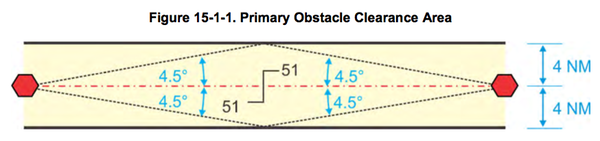
b. System accuracy. System accuracy lines are drawn at a 4.5-degree angle on each side of the course or route (see figure 15-1-1). The apexes of the 4.5-degree angles are at the facility. These system accuracy lines will intersect the boundaries of the primary area at a point that is approximately 50.82 NM from the facility (normally 51 NM is used). If the distance from the facility to the changeover point (COP) is more than 51 NM, the outer boundary of the primary area extends beyond the 4 NM width along the 4.5-degree line (see figure 15-1-2). These examples apply when the COP is at midpoint. Paragraph 15-1-7 covers the effect of offset COP or dogleg segments.

[Class A Offshore/Control Airspace Areas are identified as “High” (e.g., Atlantic High; Control 1154H). Class E areas are identified as “Low” (e.g., Gulf of Mexico Low, Control 1141L). These areas provide controlled airspace where there is a requirement to provide IFR en route ATC services, and to permit the application of domestic ATC procedures in that airspace for separation purposes. Ref.]

Class G

Airspace not assigned in Subpart A, B, C, D, E, or H of this order [FAA Order 7400.11A] is uncontrolled airspace and is designated as Class G airspace. There is no airspace within the United States designated as Class F.

AIM 3-5-6 Terminal Radar Service Area (TRSA)

a. Background. TRSAs were originally established as part of the Terminal Radar Program at selected airports. TRSAs were never controlled airspace from a regulatory standpoint because the establishment of TRSAs was never subject to the rulemaking process; consequently, TRSAs are not contained in 14 CFR Part 71 nor are there any TRSA operating rules in 14 CFR Part 91. Part of the Airport Radar Service Area (ARSA) program was to eventually replace all TRSAs. However, the ARSA requirements became relatively stringent and it was subsequently decided that TRSAs would have to meet ARSA criteria before they would be converted. TRSAs do not fit into any of the U.S. airspace classes; therefore, they will continue to be non-Part 71 airspace areas where participating pilots can receive additional radar services which have been redefined as TRSA Service.

b. TRSAs. The primary airport(s) within the TRSA become(s) Class D airspace. The remaining portion of the TRSA overlies other controlled airspace which is normally Class E airspace beginning at 700 or 1,200 feet and established to transition to/from the en route/terminal environment.

c. Participation. Pilots operating under VFR are encouraged to contact the radar approach control and avail themselves of the TRSA Services. However, participation is voluntary on the part of the pilot. See Chapter 4, Air Traffic Control, for details and procedures.

d. Charts. TRSAs are depicted on VFR sectional and terminal area charts with a solid black line and altitudes for each segment. The Class D portion is charted with a blue segmented line..

A few, like Harrisburg International, have complicated layers and rings. Palm Springs is much simpler. Some are very large and shaped more like Class B airspace. Wilkes-Barre, Elmira and Binghamton are examples.

Search FAR/AIM and FAA Publications

December 28th, 2007

Search the AIM


Pilot Controller Glossary


FAA.gov


Searching the FARs is a bit more complicated.
The FARs search will look in Code of Federal Regulations Title 14: Aeronautics and Space for the term. Many of the sections are extremely long, so finding the term on the page can be difficult. I’ve been using two part process to narrow the search.

First click on the google link and see how long it is. If the page is really long I then use the search feature in my browser to look for the words on the page. Suppose I’m looking for regulations covering tachometers and I’m a Part 91 operator, I’d use the search term “tachometer Part-91”. One of the first few links looks like it has what I’m looking for. It has just § 91.205 on required equipment for VFR, IFR, and Instrument flight. It is fairly short so I can scan it easily. This link contains all of Part 91. It’s way too long to scan. Put the word “tachometer” into the browser’s search function and use it to look for the word on the page. Another way to search the FARs is through the government’s eCFR site.

FARs


FAA Books on-line as PDFs

A Google search can find words that are in a PDF but it can’t highlight them in the actual PDF document. On the second line of the search result are the words, “File Format: PDF/Adobe Acrobat – View as HTML”. Click on the “View as HTML” link. The words in your search result will be highlighted. Look for them, or if it is a very long page, use the browser search to find the result you are looking for. If you are sure you have the right document you can download it and use your PDF viewers search function to look for words. The FAA has most of their publications on-line as PDFs. Unfortunately, a lot of them are scanned versions of the book and so are not searchable. The ones below are searchable.

Instrument Flying Handbook


Aviation Instructor’s Handbook


Procedures for Handling
Airspace Matters


Pilot Outlook—Instrument Flying Handbook

This is a non-PDF version of the Instrument Flying Handbook on the Pilot Outlook website. Note that it may not be kept up to date, so be careful in using it.


Civil “Local” NOTAMs will become NOTAM “D”s effective January 28, 2008

December 28th, 2007

NOTAMs Notice N JO 7930.85 amends FAAO 7930.2K NOTAM MANUAL effective January 28, 2008

www.FAA.gov Nov 29, 2007: NOTAMs Notice N JO 7930.85 amends FAAO 7930.2K NOTAM MANUAL effective January 28, 2008. Nov 27 This notice provides policy and procedural guidance and interim operating procedures to Federal Aviation Order (FAAO) 7930.2 Notices to Airmen (NOTAMs). NOTAMS can be found on-line here. NOTAMs for specific airports can be found here. NOTAMs for your route of flight can be found here.

D Notams

Click here for pdf.

From the order

4.a.e. All D NOTAMs shall have one of the following keywords as the first part of the text:
RWY, TWY, RAMP, APRON, AD, OBST, NAV, COM, SVC, AIRSPACE, (U), or (O).

(1) RWY (Runway)

EXAMPLES-
!STL STL RWY 12L/30R CLSD EXC TXG

!LEX LEX RWY 5 REIL OTS

!PRC SJN RWY 13/31 NOW RWY 14/32

(2) TWY (Taxiway)

EXAMPLES-
!LNS LNS TWY A LGTS OTS

!DSM DSM TWY P1, P3 CLSD

(3) RAMP (Ramp)

EXAMPLE –
!DSM DSM RAMP SOUTH CARGO RAMP CLSD

(4) APRON (Apron)

EXAMPLES-
!ATL ATL APRON NORTH TWY L3 APRON CLSD

!BNA BNA APRON NORTH APRON CLSD

(5) AD (Aerodrome includes airport, heliport, and helipads)
NOTAMs pertaining to aircraft operations on or within 5 SM of an aerodrome, which
encompasses airport, heliport, helipad, and maneuvering area, that is not covered under
runways, taxiways, ramps, aprons, obstructions, navaids, services, communications, or airspaces.

EXAMPLES-
!LAL LAL AD GRASS LDG STRIP LCTD 400 S RWY 9R/27L 1700 X 55 AVBL VMC DALGT PPR SUN N
FUN WEF 0804151100-0804232359

!CDB AK05 AD CLSD PERM

!RIU O88 AD HELI DCMSND

!AOO PA06 AD CLSD TSNT

!BET BET AD CLSD EXC SKI

!AOO 29D AD CLSD EXC PPR 0330-1430 MON-FRI

!BUF D67 AD CLSD EXC HI-WING ACFT

!CEW CEW AD CLSD WEF 0709041400-0709041800

!CDB AKA AD OPEN

!CLE 15G AD NOW PUBLIC

!CLE 15G AD NOW PRIVATE

(6) OBST (Obstructions, including obstruction lighting outages)

EXAMPLES-
!MIV N52 OBST TOWER 580 (305 AGL) 7 SW LGTS OTS (ASR NUMBER) TIL 0712302300

!PIE CLW OBST CRANE 195 (125 AGL) .25 NE (2755N08241W) TIL 0711032000

NOTE: Insert latitude/longitude, if known, immediately after cardinal direction in the format shown above.

(7) NAV (Navigation Aids)

EXAMPLE-
!PNC PER NAV VOR UNUSBL 045-060 BYD 20 BLW 2000

(8) COM (Communications)

EXAMPLES-
!DCA PSK COM RCO OTS

!IPT IPT COM VOR VOICE OTS

(9) SVC (Services)

EXAMPLES-
!MIV MIV SVC FUEL UNAVBL TIL 0709301600

!SHD SHD SVC TWR 1215-0300 MON-FRI/1430-2300 SAT/1600-0100/SUN TIL 0709170100

(10) AIRSPACE (Airspace)

EXAMPLES-
!CHO CHO AIRSPACE HELIUM BALLOONS 30 NE 1 NMR 10000/BLW WEF 0710121800-0710121830

!BKW BKW AIRSPACE PYROTECHNIC DEMO 1000/BLW 8 W .5 NMR AVOIDANCE ADZD WEF
0712312230-0712312300

(11) (U) – Unverified Aeronautical Information (for use only where authorized by
Letters of Agreement).

Movement area or other information received that meets NOTAM
criteria and has not been confirmed by the Airport Manager (AMGR) or their designee. If Flight
Service is unable to contact airport management, Flight Service shall forward (U) NOTAM
information to USNS. Subsequent to USNS distribution of a (U) NOTAM, Flight Service will
inform airport management of the action taken as soon as practical. Any such NOTAM will be
prefaced with ‘(U)’ as the keyword and followed by the appropriate keyword contraction, as set
forth in this Policy, following the Location Identifier.

EXAMPLE-
!ORT 6K8 (U) RWY ABANDONED VEHICLE

(12) (O) – Other Aeronautical Information.

Aeronautical information received from any authorized source that may be beneficial to aircraft
operations and does not meet defined NOTAM criteria. Any such NOTAM will be prefaced with
‘(O)’ as the keyword following the Location Identifier.

EXAMPLE-
!LOZ LOZ (O) CONTROLLED BURN OF HOUSE 8 NE APCH END RWY 23 WEF 0710211300-
0710211700

f. Any NOTAM associated with “Personnel and Equipment Working” (PAEW), will be
associated with RWY, TWY, RAMP, or APRON and a direction from the associated
movement area, as appropriate.

EXAMPLES-
!CHO CHO RWY 23 PAEW FIRST 500 ALONG SE SIDE

!SBY SBY TWY E PAEW SOUTH SIDE BTN RWY 5/TWY G

Links:
FAA-Air Traffic Plans These notices are about halfway down the page—near the end of the notices section.
NBAA Discussion
AOPA

Instruments – Airspeed Indicator

December 27th, 2007

Some of the speeds you need to know are marked on the airspeed indicator but many are not. VS1, VS0, VFE, VNO, and VNE are almost always color coded on the ASI because they are required by the FAA. (Airplanes weighing 12,500 pounds or less, manufactured after 1945, and certificated by the FAA, are required to have airspeed indicators marked in accordance with a standard color-coded marking system. This system of color-coded markings enables a pilot to determine at a glance certain airspeed limitations that are important to the safe operation of the airplane. Handbook of Aeronautical Knowledge p 6-6)

Red is never exceed—the maximum allowable airspeed of the airplane, yellow is cautionary range—smooth air operation only, green is normal, white is normal flaps operating range. The bottom of the white arc indicates the stall speed with flaps extended, the bottom of the green arc is stall speed without flaps extended.

Airspeed Indicator - Max speed 160
Cessna 152 Airspeed Indicator
Airspeed Indicator - Max speed 200
Cessna 182 Airspeed Indicator
Airspeed Indicator - Max speed 240
Cessna T210 Airspeed Indicator


At first glance these indicators appear to be different, but they all follow the same pattern as described in the table below. The 152 ASI shows airspeed in knots with a cutout that rotates with the needle showing MPH. The 182 and 210 ASIs show speed as MPH on the outer ring but the 172 has a fixed inner ring for knots and the 210 has a cutout like the 152. It also has an outer bezel that uses temperature and pressure altitude to show true airspeed (TAS) in MPH. Note also the colors. The 152 is a relatively new airplane compared to the 182 (1961) and 210 (1973) and its colors haven’t yellowed over time.

Airspeed Indicator Color Coding
VSpeed Description Color Code
VS1 Stall speed “clean” Bottom of the green arc
VS0 Stall speed “dirty” Bottom of the white arc
VFE Maximum speed—Flaps extended Top of the white arc
VNO Maximum structural cruising speed Top of green arc
VNE Never exceed speed Red line
Normal operating range Green arc
Flaps operating range White arc
Caution range Yellow arc

Stall speed “clean”—Flaps up, Gear up, max weight, power off.
Stall speed “dirty”—Flaps down, Gear down, max weight, power off. Bottom of the white arc.
Caution range—Operate only in smooth air with no turns.

Airspeed Indicator Additional Speeds
VSpeed Description Explantion
VX Best angle climb speed Obstacle clearance speed
VY Best rate climb speed Fastest climb to altitude
VA Maneuvering speed Maximum speed in turbulance
VLE Maximum landing gear extended speed Max speed for flying with gear down
VLO Maximum landing gear operating speed Max speed for extending or retracting gear
VFE-10° Maximum speed—Flaps 10° Flaps extended Some planes allow 10° of flaps outside of the white arc
VBG Best glide speed Airspeed for maximum distance power-off glide
VYSE Single engine rate of climb speed Twin engine, sometimes marked with a blue line
VR Rotation speed Speed for initiating rotation
VREF Reference landing approach speed Usually 1.3 x VS1

VA is dependent on weight. Higher weight is higher V speed. There is approximately a 1 percent decrease in maneuvering speed for every 2% increase in weight. Another general rule of thumb is that if you look at the ASI as a clock, VA is at 6:30.

VBG is also dependent upon weight. Best Glide Speed decreases as total aircraft weight decreases
VX increases slightly with altitude.

V-Speeds
Cessna T210L N59049
V Speed MPH Knots
VX  82  71
VY 110  96
VA 135  96
VR  70  61
VLE 160 139
VLO 160 139
VFE 10° 160 139
VFE 120 104
VNE 225 196
VS0  65  56
VS1  75  65
VBG 85-95 74-83
V-Speeds – IAS
Cessna 182F N771EE
V Speed MPH Knots
VX 20° Flaps  60  52
VY 84  73
VA 128-123 111-107
VR  60  52
VLE NA NA
VLO NA NA
VFE 10° 110  96
VFE 110  96
VNE 193 168
VS0  40  35
VS1  60  52
VBG 85-95 74-83


Links:
Surecheck Aircraft V Speeds is a book that is available from PilotStore.com that claims to have V-Speeds for over 80 aircraft. I haven’t seen it but it sounds like something that would be useful if you fly a lot of different aircraft.

Whitt’s Flying has lots of information on airspeeds, but is a bit disorganized.

Wikipedia has lots of information on V-speeds that appears to be correct.

The FARs § 1.1 General definitions. define some V-speeds.

VA means design maneuvering speed.

VB means design speed for maximum gust intensity.

VC means design cruising speed.

VD means design diving speed.

VDF / MDF means demonstrated flight diving speed.

VEF means the speed at which the critical engine is assumed to fail during takeoff.

VF means design flap speed.

VFC / MFC means maximum speed for stability characteristics.

VFE means maximum flap extended speed.

VH means maximum speed in level flight with maximum continuous power.

VLE means maximum landing gear extended speed.

VLO means maximum landing gear operating speed.

VLOF means lift-off speed.

VMC means minimum control speed with the critical engine inoperative.

VMO / MMO means maximum operating limit speed.

VMU means minimum unstick speed.

VNE means never-exceed speed.

VNO means maximum structural cruising speed.

VR means rotation speed.

VS means the stalling speed or the minimum steady flight speed at which the airplane is controllable.

Chart Exercise – Departure: Setting the Radios

December 21st, 2007

Departure procedures can often involve changing radios and radials several times in less than 10 minutes. Setting up the GPS and radios in advance can make the process much easier. I’m still learning so I like to write out the entire departure procedure and think through what happens at each altitude and turn.

If you have two radios, it’s even easier. Set the top radio up as the one to use for contacting the airport tower/CTAF and ground. If you are using a GPS for the first radio, these frequencies are easy to find and load from the database. The VOR should be set to the course to be flown. Set the bottom radio up for en route. The VOR on the bottom radio should be set to the radial that defines the first intersection.

The KSBP CREPE3.PRB departure is fairly straightforward so we’ll start with that. The NACO chart is below. Click on it for a larger version or here for a printable PDF version. Note that we’ve already covered the departure minimums here.

CREPE3 Departure

The departure uses the localizer for the initial climb out. Set the first radio to 109.7 and the OBS to 290°. Because it is a localizer, the OBS setting has no effect, but it is a good habit to always set the course index when using the CDI. We can identify it on the ground.

We need the second radio to identify CREPE. Set it to 114.3 and put 196° at the top of the CDI. We can’t identify it on the ground, so turn the volume on just a little so we’ll hear it when it comes in. The VOR is on our right so the needle will start on the right and move to the center. We can estimate when it will come alive by knowing that each dot on the CDI is 2° so full scale deflection is 10°, possibly 12° when the needle starts moving to the center. The CDI measures angular deviation, so the farther from the VOR you are the greater the distance from the course.

Lateral Course Deviation
by Distance from the VOR
Distance from VOR Dots Lateral Distance
1 nm   1 dot   200 feet
2 nm   1 dot   400 feet
30 nm   1 dot   1 nm
60 nm   1 dot   2 nm
Full Deflection
1 nm   5 dots  1,000 feet
2 nm   5 dots  2,000 feet
30 nm   5 dots  5 nm
60 nm   5 dots  10 nm
Full Deflection – Miles
6 nm   5 dots  1 nm
12 nm   5 dots  2 nm
18 nm   5 dots  3 nm
24 nm   5 dots  4 nm

CREPE is 22 nm from PRB. We are not approaching it on a DME arc, so the distance from PRB to our track is greater than 22 nm and decreasing as we get closer to CREPE. From the chart above we see that we the needle should start to move about 4 nm from CREPE. At 120 kts, this is about 2 minutes. From the table above, we can see that full deflection follows about a 6:1 rule, while 1 dot deflection follows a 30:1 rule.

For CREPE3.PRB we make a right turn as the needle hits the outer edge of the center ring of the CDI. We are on the 196° radial and we’ll fly a heading of 016° TO the VOR so we want 016 at the top of the #1 OBS. So before we leave the ground, we want to set PRB in the standby position. After we make the turn, ident the VOR and do the 5 T’s—Turn, Time, Twist, Throttle, Talk. Since we don’t have any information on the next leg, there is nothing to guide us on selecting the standby position for the #2 VOR.

CREPE3.MQO gets a little more complicated, but not much. Set the radios up as before. Now when we get to CREPE we turn left, and fly outbound on the 196° radial. The #2 VOR is already set and identified, and we are only flying 5 nm so if we fly the #2 radio and have MQO in standby on #1, it will simplify the workload. Identify MQO and put the radial we are intercepting at the top of the CDI, with a FROM indication. The VOR is on our left, so the needle will move from left to right. We are only 8-10 miles from the VOR so full scale deflection is about 1.3 nm. We’ll only have about 40 seconds while the needle goes from full scale to centered. (At 120 kts – maybe less time if we are out of our climb and flying at cruise speed.) Turn and twist the OBS to to 090° TO.

CREPE3.FRAMS is set up about the same way as CREPE3.PRB. Set the radios up the same as CREPE3.PRB. Now when we get to CREPE we twist the OBS to 204°. The needle should be just to the left of the fourth dot. When the needle hits the outer edge of the circle, turn left, and fly outbound on the 204° radial. Fly the #2 VOR for 2 nm. If MQO is in standby on #1, it will simplify the workload. Identify MQO and put the radial we are intercepting (292°) at the top of the CDI, with a FROM indication. The VOR is on our left, so the needle will move from left to right. We are only 11-12 miles from the VOR so full scale deflection is about 2 nm. We’ll only have about 60 seconds while the needle goes from full scale to centered. (At 120 kts – maybe less time if we are out of our climb and flying at cruise speed.) Turn and track outbound on the 292° radial.

VORs

December 19th, 2007

VORs operate within the 108.0 to 117.95 MHz frequency band and have a power output necessary to provide coverage within their assigned operational service volume. They are subject to line-of-sight restrictions, and the range varies proportionally to the altitude of the receiving equipment. Range also depends on the class of the VOR—Terminal, Low Altitude, or High Altitude. If you are using airways, you generally don’t need to be concerned about the service volume because the MEAs guarantee reception of the VOR signal unless the chart shows a VOR gap. If you are planning an off-airway route, then you need to concern yourself with the service volumes. And of course, you need to know them for the written.

The Service Volume slopes up gradually to 1,000′ and then look like a a cylinder for Terminal and Low Altitude VORs, and looks like a cylinder with rings of various diameters attached for High Altitude VORs.

High SSV VOR

Low SSV VOR   Terminal VOR

VOR/DME/TACAN Standard Service Volumes
SSV Class Designator Altitude and Range Boundaries
T (Terminal) From 1,000 feet above ground level (AGL) up to and
including 12,000 feet AGL.
 25 nm
L (Low Altitude) From 1,000 feet AGL up to and
including 18,000 feet AGL
 40 nm
H (High Altitude) From 1,000 feet AGL up to and including 14,500 feet AGL
From 14,500 AGL up to and including 18,000 feet AGL
From 18,000 feet AGL up to and including 45,000 feet AGL
From 45,000 AGL up to and including 60,000 feet AGL
 40 nm
100 nm
130 nm
100 nm

Most books that I’ve seen leave out the coverage below 1,000’—implying that there is no coverage. The coverage gradually increases from ground level to 1,000′ as shown below.

VOR Terminal SSV Low Edge   VOR High/Low SSV Low Edge

Note that Terminal VORs have coverage all the way to the ground out to 5 miles and at 200’AGL coverage is 10 nm. So you don’t have to worry about the service volume near the airport, where you are most likely to use a Terminal VOR.

VORs are line of sight, so you do have to worry about coverage if mountains get in the way. The A/FD will tell you where the VOR is unusable. For example, the Guadalupe Terminal VOR (GLJ) near Santa Maria, CA is unusable 300°-325° beyond 10 NM below 3000′. The Snow Low VOR (SXW) used in the LDA approach to Eagle County, CO is unmonitored 0600-1300Z‡ and unusable 115°-135° all altitude and distance and unusable 310°-355° all altitude and distances. You might want to be sure the VOR is operating before you start the approach if you are arriving late at night or early morning.

VOR Check

December 19th, 2007

If a VOR is to be used for navigation under IFR flight rules—regardless of weather conditions—it must be operationally checked within the preceding 30 days. The check can be done with any of the following six methods:

1. VOR test signal at a certificated repair station. ±4° bearing error.
2. FAA VOR test facility (VOT). ±4° bearing error.
3. Designated surface checkpoint. ±4° bearing error.
4. Airborne checkpoint. ±6° bearing error.
5. Inflight check using prominent ground point on an airway. ±6° bearing error.
6. Dual VOR check. ±4° bearing difference between VOR readings.

You must enter the date, place, bearing error, and sign the aircraft log or other record. Note: You don’t need to keep a permanent record of the check, just the current one. We use a small spiral notepad.

Notes:
1. The signal is normally 108.0 MHz and repair stations are not permitted to radiate the VOR test signal continuously. In general, this option is mostly used if there is a problem with the VOR. The bearing is selectable.

2. Listed in the back of the A/FD as “VOR Test Facilities (VOT)”, They are frequently found at larger airports. The AF/D often has a note saying that they are “unusable except in the runup area”. They transmit the 0° radial. If the OBS is set to 0° there should be a FROM indication, if the OBS is set to 180° there should be a TO indication. An RMI (Radio Magnetic Indicator) will indicate 180 degrees on any omni-bearing selector (OBS) setting.

3. Listed in the back of the A/FD Chart Supplement as “VOR Receiver Checkpoints”. From looking at the A/FD Chart Supplement it appears that most of the designated surface checkpoints are at airports that have a VOR on the field or nearby. The A/FD Chart Supplement has the location on the field where the check should be made, the DME distance, and the radial. There are very few that are farther than 6 nm away. Very few have designated markings on the field, instead they are at taxiway intersections, runup areas, in front of the terminal, etc.

4. Listed in the back of the A/FD Chart Supplement as “VOR Receiver Checkpoints” under the name of the VOR. Similar to the ground checkpoints except that they also contain an altitude. Many of them are located over the approach end of the runway at TPA. Some VORs have airborne checkpoints at the approach end of several airports.

5. If no check signal or point is available, while in flight—
(i) Select a VOR radial that lies along the centerline of an established VOR airway;
(ii) Select a prominent ground point along the selected radial preferably more than 20 nautical miles from the VOR ground facility and maneuver the aircraft directly over the point at a reasonably low altitude.

An easy way to do this is to fly directly over one VOR on an airway and note the radial for the next VOR on the route. They are usually far enough apart that you can test sensitivity. For example, V113 is defined by the 179° radial FROM PRB and the 358° radial FROM MQO. MQO is easy to see from the air, it’s a white tower on a mountaintop surrounded by a clearing. It’s also 25 miles from PRB so it’s far enough away that out-of-calibration errors will show up. I flew over MQO at 3,000′ and noted the PRB radial. It matched exactly. I logged it in the plane usage log with the date, location, bearing error, and my name as per the regs. I also entered it into the Garmin SL30 so that the last VOR check date is displayed when the radio is turned on.

6. The dual-VOR check is probably the most common way to check VORs. If you have two VORs that are independent except for the antenna, then center both to the same radial and note the bearing. The difference between the bearings on the two VORs must be less than 4°.

Ways you _cannot_ check your VORs.
1. Using the Radio Aids to Navigation section for an airport in the A/FD, note the radial and distance to the listed VORs.
2. Use a sectional to determine the radial of a prominent ground point not on an airway.
3. Use your GPS to determine the radial of an airborne or ground location.
4. Perform a VOR check and then use the VOR to determine the radial of a prominent landmark or ground location.

The easiest way to log the VOR check is to keep a small notebook in the plane and make a note in it each time you make the VOR check. Since the PIC is responsible for the VOR check, if you fly several airplanes, it might be a good idea to keep a notebook with your flight bag and log the VOR checks in it for each plane.

One check you can make, that is not required, is to center the needle and note the bearing. Turn the OBS 2°. The needle should now be centered over the first dot, repeat for each dot until you are 10° from the starting point. The needle should be over the last (5th) dot.

Refer to to AIM 1-1-4. VOR Receiver Check or FAR §91.171 for details.

FAA Knowledge Tests

Try your hand at answering some questions on VORs from the tests.

Video

If you like video explanations, here’s Garry Wing telling you all about it.

Landing Under IFR

December 18th, 2007

14 CFR §91.175 Takeoff and landing under IFR.

(c) Operation below DA/ DH or MDA.
Except as provided in paragraph (l) of this section, where a DA/DH or MDA is applicable, no pilot may operate an aircraft, except a military aircraft of the United States, below the authorized MDA or continue an approach below the authorized DA/DH unless—

(1) The aircraft is continuously in a position from which a descent to a landing on the intended runway can be made at a normal rate of descent using normal maneuvers, and for operations conducted under part 121 or part 135 unless that descent rate will allow touchdown to occur within the touchdown zone of the runway of intended landing;

(2) The flight visibility is not less than the visibility prescribed in the standard instrument approach being used; and

(3) Except for a Category II or Category III approach where any necessary visual reference requirements are specified by the Administrator, at least one of the following visual references for the intended runway is distinctly visible and identifiable to the pilot:

(i) The approach light system, except that the pilot may not descend below 100 feet above the touchdown zone elevation using the approach lights as a reference unless the red terminating bars or the red side row bars are also distinctly visible and identifiable.

(ii) The threshold.
(iii) The threshold markings.
(iv) The threshold lights.
(v) The runway end identifier lights.
(vi) The visual approach slope indicator.
(vii) The touchdown zone or touchdown zone markings.
(viii) The touchdown zone lights.
(ix) The runway or runway markings.
(x) The runway lights.

San Francisco International (KSFO)

Scroll the view to the approach end of the 28L and 28R runways and zoom in. You can see the approach lighting system (ALS) extending out into the bay. There is an overrun area indicated by the chevrons at the end of the runway. The chevrons indicate that it is not usable and in fact it is an Engineered materials arresting system (EMAS) that is designed to catch aircraft that would otherwise overrun the runway and end up in the bay.

The white arrows indicate the displaced threshold. It may be used for taxiing, takeoff, and landing rollout, but not for touchdown. The striped bars are the threshold markings. The number of stripes relate to the width. The designation markings are next. These are typically referred to as “the numbers” although in this case there are also letters. The runway centerline extends just past the numbers and continues down the runway. The touchdown zone markings are next, followed by the aiming point markings (solid white bars 1,000′ from the end of the runway). The first set of touchdown zone marking consist of two sets of three stripes located 500′ from the runway threshold. The runway aiming point is 1,000′ from the threshold. Additional touchdown zone markings after the aiming point are spaced at 500′ increments. There are two sets with two stripes followed by two sets with one stripe. Along the side of the runway are side stripes. The touchdown zone marking and the side stripes are only present on runways with a precision approach. Refer to AIM 2-3-3 for details.

If you drag the image to show the intersection runways, you can see that 19L has an approach lighting system extending into the bay for the precision approach and 19R does not. The markings on 19R indicate that it should have a precision approach, but there are currently no instrument approaches for it or either 1L or 1R.

This view you can see the following elements required to operate below MDA/DA.
(i) The approach light system. YES
(ii) The threshold. YES
(iii) The threshold markings. YES
(iv) The threshold lights. NO – but it isn’t dark.
(v) The runway end identifier lights. SORT OF – if you zoom in you can see where they are.
(vi) The visual approach slope indicator. NO – but they have a PAPI
(vii) The touchdown zone or touchdown zone markings. YES
(viii) The touchdown zone lights. NO – but it isn’t dark.
(ix) The runway or runway markings. YES – several things here
(x) The runway lights. NO – but it isn’t dark.

If you visualize the runway, it should help remember the 10 things required to land. You can also group the items in the following list. You actually get 12 things because my list has a place for runway markings and TDZ markings and the FAR combines them in one item.

  • Lighting—Approach lighting system (100′ above TDZE), REIL, or VASI
  • Threshold, markings, lights.
  • TDZ, markings, lights
  • Runway, markings, lights

Definitions from the Pilot/Controller Glossary

Threshold—The beginning of that portion of the runway usable for landing.
Displaced Threshold—A threshold that is located at a point on the runway other than the designated beginning of the runway.
Touchdown zone—The first three thousand feet of the runway, beginning at the threshold. Note: This is why there are three sets of stripes along the runway. The first set and the aiming point are in the first 1,000′. Two sets with two stipes are in the second 1,000′. Two sets with 1 stripe are in the final 1,000′ of the TDZ.
Airport Lighting—This section of the glossary is fairly long. Click on this link and look for “airport lighting”

Climb and descent rates

December 18th, 2007

ATC Climb or Descent Clearance – IFR and VFR

AIM 4-4-10 d. When ATC has not used the term “AT PILOT’S DISCRETION” nor imposed any climb or descent restrictions, pilots should initiate climb or descent promptly on acknowledgement of the clearance. Descend or climb at an optimum rate consistent with the operating characteristics of the aircraft to 1,000 feet above or below the assigned altitude, and then attempt to descend or climb at a rate of between 500 and 1,500 fpm until the assigned altitude is reached. If at anytime the pilot is unable to climb or descend at a rate of at least 500 feet a minute, advise ATC. If it is necessary to level off at an intermediate altitude during climb or descent, advise ATC, except when leveling off at 10,000 feet MSL on descent, or 2,500 feet above airport elevation (prior to entering a Class C or Class D surface area), when required for speed reduction.

AIM 5-3-3
a. The following reports should be made to ATC or FSS facilities without a specific ATC request:
1. At all times.
… (c) When unable to climb/descend at a rate of a least 500 feet per minute….

Instrument Departure Procedures

AIM 5-2-8 b.1 1. Unless specified otherwise, required obstacle clearance for all departures, including diverse, is based on the pilot crossing the departure end of the runway at least 35 feet above the departure end of runway elevation, climbing to 400 feet above the departure end of runway elevation before making the initial turn, and maintaining a minimum climb gradient of 200 feet per nautical mile (FPNM), unless required to level off by a crossing restriction, until the minimum IFR altitude. A greater climb gradient may be specified in the DP to clear obstacles or to achieve an ATC crossing restriction. If an initial turn higher than 400 feet above the departure end of runway elevation is specified in the DP, the turn should be commenced at the higher altitude. If a turn is specified at a fix, the turn must be made at that fix. Fixes may have minimum and/or maximum crossing altitudes that must be adhered to prior to passing the fix.

Implications for IFR flight

From the above information, it appears that enroute courses are designed with a minimum climb rate of 500 fpm. When approaching a fix with an altitude change, that does not have a Minimum Crossing Altitude, you may cross the fix at the current Minimum Enroute Altitude and then climb at least 500 fpm to the new MEA. Departure procedures assume that you will be climbing with at least 200 feet per nautical mile climb rate (unless a higher rate is specified). If you are complying with any minimum climb rates on a departure procedure, and you arrive at the fix that begins a portion of the DP with a higher MEA, then you may cross the fix at your current altitude and climb to the new MEA. You must climb at least 500 fpm or (if specified) at the rate in the DP. If you are unable to do so you must notify ATC.

Chart Exercise 2 – Departure: Minimum Climb Gradient

December 17th, 2007

The KSBP Crepe3.PRB departure is fairly straightforward so we’ll start with that. The NACO chart is shown below. Click here for PDF version or here for a larger version in a new window.

Crepe3 Departure

The first thing to note about this departure is that it has a minimum climb gradient (275′ per nm to 1700′ with standard minimums) _or_ takeoff minimums of 1300-2. The AIM (5-2-8) tells us the options the DP designer has when there is an obstacle that penetrates a 40:1 obstacle identification surface. This designer gave us a choice. If we can see 1,300 agl then we can see the obstacle and presumably avoid it. Otherwise we must be able to climb at a rate that is faster than the standard 200′ per nm.

We don’t know what the obstacle is by looking at the DP, however; the ILS approach plate1 shows an obstacle just past HASBY at 100′ above ground elevation of 567′. There is a radio tower on a small hill just about where the obstacle is so that’s probably what the DP designer is concerned about. It’s pretty flat otherwise and HASBY is 2.4 nm from the runway so let’s see what happens if we climb at 275’/nm for 2.4 nm. We will have climbed 660′. Add 198′ for the TDZE elevation and 35′ crossing the end of the runway and we should be at 893′. That will put us 226′ above the obstacle even if we have strayed off course. (Note that the localizer approach MDA without HASBY is 1040′, so unless we can be sure we’re past HASBY the approach keeps us 373′ above the obstacle.)

Referring to the approach chart again, let’s figure out where we are when we are at 1,700′ MSL. The airport is 198′ and the designer of the DP assumes we cross the threshold at 35′. So (1700-198-35)/275 = 5.3 nm from the airport. CREPE is 13 nm from the airport so we have 7.7 nm to go after reaching 1,700′. If we drop back down to the minimum climb gradient of 200′ per nm, we would climb an additional 1,540′. Then we would cross CREPE at 3,240′. If you are flying the CREPE3.FRAMS it should be no problem to go from 3,240′ to 4,000′, especially since you are flying over the ocean. The Morrow Bay transition altitude is 3,500′ so you are fine there if you continue your climb for another mile.

CREPE3.PRB is a different story. The altitude for the transition is 5,000′ and there are mountains about 5 nm from CREPE. If you fly the entire departure at 275′ per nm then, since CREPE is 13 nm from the airport 13 nm * 275′ per nm yields 3,575′. Add the airport elevation of 198′ and 35′ above the departure end of the runway on takeoff and you are at 3,808′. Continue climbing after the turn and you will be at 5,000′ in 4.3 nm, before you get to the mountains.

Suppose you wanted to get to 5,000′ before reaching CREPE, then (5,000-198-35)/13 = 366.7′ per nm. NACO has a rate per minute chart that you need to use to estimate the required groundspeed. Jeppesen has the appropriate portion of the chart on the plate but also has the entire chart in the front of the chart book. The chart is also included in the Instrument Written Supplement, click here to view in a window. Notice that we’ll need to interpolate to get 366.7′. It is about 1/3 the distance between 350 and 400 so, for a given groundspeed, add 1/3 the difference between the climb rate per minute for 400 and 350 to the rate for 350. Looking at 90 kts, the calculation is (600-525)/3 + 525 = 25 + 525 = 550′ per min. If you climb out at 550′ per minute and your ground speed is no more than 90 kts, then you’ll be at 5,000′ when reaching CREPE. If your groundspeed is less than 90 kts, then you’ll have no problem, however, if it is more then you’ll need to increase the climb rate or decrease your groundspeed.

1Jeppesen and NACO often have differences in how they show obstacles. Jeppesen shows a terrain elevation of 567′ and an obstacle at 667′. NACO shows just the obstacle at 567’±. The location of other obstacles is also different on the two charts. If you a flying where you are supposed to, it shouldn’t be an issue. If you are ducking under or around a cloud, you could be surprised.

Chart Exercise 1 – Enroute/Sectional

December 13th, 2007

Some of the symbols on the chart stick in my mind but I have trouble remembering others, especially the ones that are not as common. Before throwing away a chart, put it to use refreshing your memory on the symbols. Pick a grid section and highlight the different symbols. If you can’t name it, look it up. If you have to think about it, find more instances on the chart an highlight them. Your chart might look like the Jepp chart below. Here is a larger view.

Jepp enroute highlighted

On the first pass through, I found the the obvious symbols: Kingman airport in blue—an airport with an IFR approach, Peach Springs—VFR only, Peach Springs VOR—High altitude with DME and HIWAS, several intersections and crossover points, and distance measurements.

On the second pass I noticed the blue line for the Special Flight rules area around the Grand Canyon. That is actually one I’d never seen before. The WYLDD/COWBY fix is a bit unusual. First, it is not on an airway, being defined by the intersection of two off airway radials. Second, usually there is an airport nearby (within 30 nm) that uses the fix as part of the approach. Because Peach Springs is in green, we know it has no IFR approaches. Kingman is rather far away for this to be part of the approach to it. Boulder City is the VOR off to the left that defines it. It is 47 nm away and 15 nm from Las Vegas. There are no airports anywhere near, but it is right at the edge of the Grand Canyon Special Flight Rules Area, so that could have something to do with it.

While I was trying to find out why it was there I stumbled on an interesting site that lets you look up waypoints (fixes). The easiest way to use it is to copy this following line into the Google or DuckDuckGo search box.


site:fallingrain.com fixname
e.g.
site:fallingrain.com wyldd

There are a couple of things that aren’t obvious on the chart. The shaded gray area is Class G airspace. In the west, that usually means high mountains. The X on the right hand side of the chart on 562 is a mileage fix that is not a reporting point. They are not especially common. There are no MOCAs or MORAs, or Minimum Crossing Altitudes on this part of the chart, just a couple of MEAs. I’ve been able to find just about every symbol used on the charts except for MAA—Maximum Authorized Altitude. I suspect there aren’t any in western states because they are required to prevent interference from other navaids and the navaids are pretty far apart in most places in the west.

Here is the same section on the NACO chart

NACO enroute highlighted

You can do the same thing with the sectional chart. The symbols are printed on the Legend section of the chart. Find an old chart and go thru the symbol legend and find all of the symbols near your home airport. Then use another chart or a section away from your home airport and look for all of the symbols. See how many you can name without them looking up. Check off the symbols you have found and then look for the ones you haven’ seen yet. Since these are on VFR charts, look for the landmarks on your next VFR trip.

If you don’t have a sectional for the area you are interested in, you can look up the airport at AOPA or AirNav and click on the sectonal. Or you can go to SkyVector and click on the charts button to look up the any sectional for the US. You can also use this site to look up information on specific airports.

Weather Sites

December 11th, 2007

Update 2017-01-04 Many of the links on this page are broken but I’m leaving it up in case you want to track them down. Some of them like the Aviation Weather page have just moved to another location on the site. Others are no longer in existence.

Here is a great place to start—the Standard Briefing page of the National Weather service.

However, this has got to be used to be the coolest weather site around. ADDS is Beta testing HEMS, a Java-based tool that has: Ceiling and Visibility Data; Radar Products; Convection Data; Saved Views; and High Resolution GIS Data. I’m especially fond of the icing and METARs maps.

The coolest weather site by far is AvnWx. They take a Google map and overlay radar, AIRMETs, SIGMETs, and PIREPs. Rolling over airports shows the METARs. A balloon above the airport shows TAFS. You can click on the screen and drag it around route and see weather along the way. Tons of features that are discussed in more detail here.

The FAA has its own Google map with overlays. It has the weather stations coded by station type, so it isn’t as nice for getting a view of the weather in an area. It does have the phone numbers for the ASOS/AWOS at each airport—not the ATIS—and it has a quick link to a 24-hour history. Start here to select a state.

The Daily Weather Map has surface weather at 7 am Eastern Time back to Jan 1, 2003. The same page has the max and min temperature; 500 millibar height contour with temperature and winds; and 24 hour rainfall. It is great for showing what happened in the last few days.

The Air Force Weather site has satellite maps and animations for the world, radar maps of the US, winds aloft maps, and pressure charts (I’m not sure what these are or how to use them).

The National Weather Service Current Watches and Warnings has state specific weather advisories. It includes things like frost warnings, dense fog advisories, flood warnings, and storms. Watches and warnings are often by county, so you can narrow down the area of interest.

The Aviation Digital Data Service has coded and decoded METARs and TAFs. You can go directly to their site or bookmark your favorites using KSBPs TAF or current METAR as your starting point. Just replace KSBP with an ICAO identifier in the URL. It is not case sensitive.

The Unisys weather site has GOES satellite images—visible, infrared, enhanced infrared, and water vapor. It also has millibar maps from 100 mb to 950 mb, and surface radar. There are also six forecasts based on different modeling techniques.

I haven’t used it but the Weather Underground has seems pretty good for an overview of the weather. The state-level view would be good for looking at alternates, and the radar views are nice too.

AOPA’s weather site recently switched to a different provider. I’m still getting used to it, but I much preferred the old site. One thing that is missing is the legends for the maps but they can be found at the Jeppesen weather legend site, which appears to be the data provider. Since they changed, I’ve been using the ADDS site mentioned above and I like it a lot.

Forecast and actual weather often differ and the FARs actually require you to report when weather differs from forecast. PIREPs are pilot reports of actual weather encountered. They can be accessed at the NOAA Aviation Weather site.

The Space Science and Engineering Center at the University of Wisconsin (link) is my new favorite for satellite pictures. It has links to GOES-East and GOES-West, and other parts of the world; an animated Real-Time U.S. Composite Satellite Image; and more cool stuff.

As more pilots get smartphones sites have been optimized for showing the weather on their small screens. AirWx Mobile is a free site with radar, METARs, and TAFs.


The content on this web site is provided for your information only and does not purport to provide or imply legal advice.
Should opinions, explanations, or discussions conflict with current FARs, other rules, regulations, or laws, then appropriate provisions of those rules, regulations, or laws prevail.
Navigation charts are provided for illustrative purposes only and are Not for Navigation.
TouringMachine.com is not responsible or liable for any errors, omissions, or incorrect information contained within this site.
Use at your own risk.
Copyright © 2002-2024 Touring Machine Company. All Rights Reserved.